SysML Example Tutorial: Griffin Space Vehicle Project
This SysML Example Tutorial features a hypothetical Griffin Space Vehicle Project example to illustrate best practices for specifying System-of-System (SoS) complexity using the Systems Modeling Language (SysML). This SysML example applies the MBSE + SysML System Architecture Framework Pattern, and llustrates numerous recursive MBSE Analysis and Design and Patterns that are both scalable and simulatable.
For a SysML primer that provides an overview of the nine (9) SysML diagram types and complementary Allocation Tables that constitute this de facto MBSE architecture modeling language standard, check out the SysML Diagram Tutorial.
Architecture «view»
The Architecture «view» layer provides a System Architecture overview applies the MBSE + SysML System Architecture Framework Pattern. The SysML Package diagrams in this layer illustrate how the System Architecture is organized into complementary Views and Viewpoints, consistent with international standards (ISO/IEC/IEEE 42010 Systems and software engineering — Architecture description)and Model-Based Systems Engineering (MBSE) best practices.
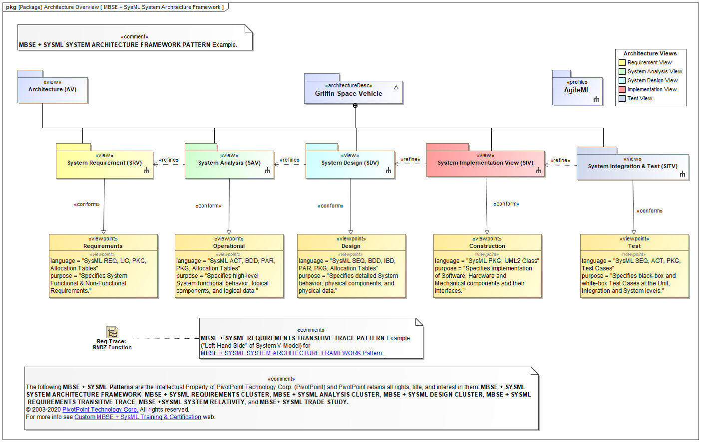
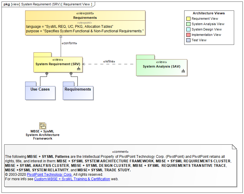
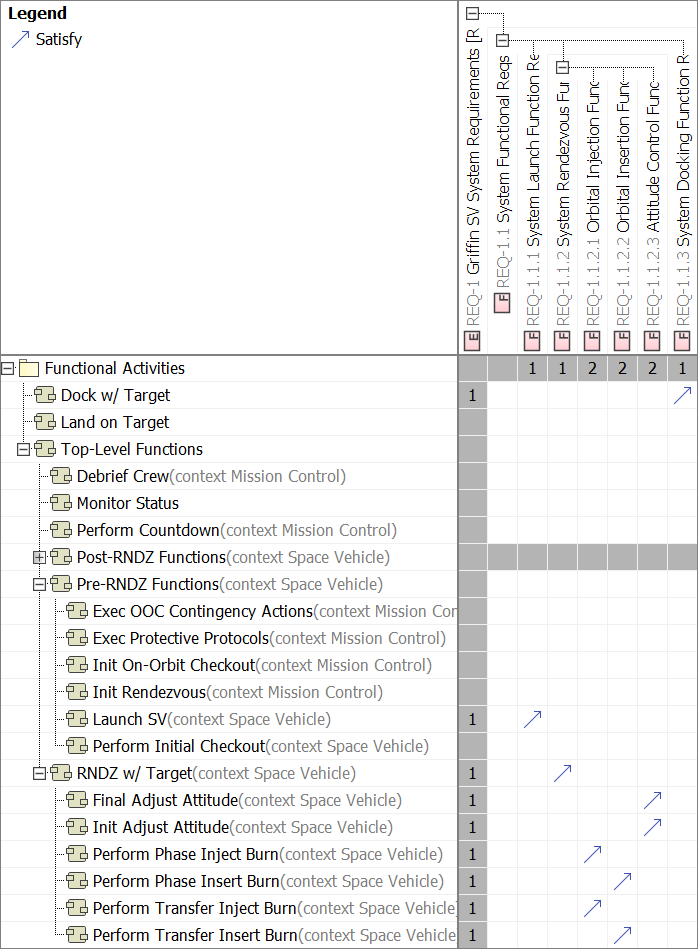
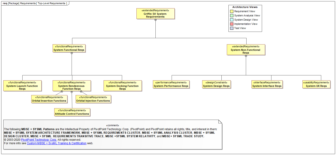
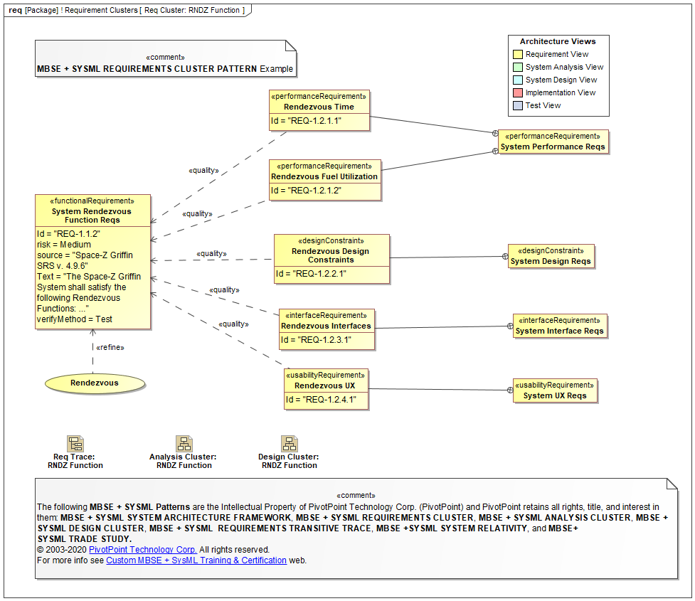
Requirement «view»
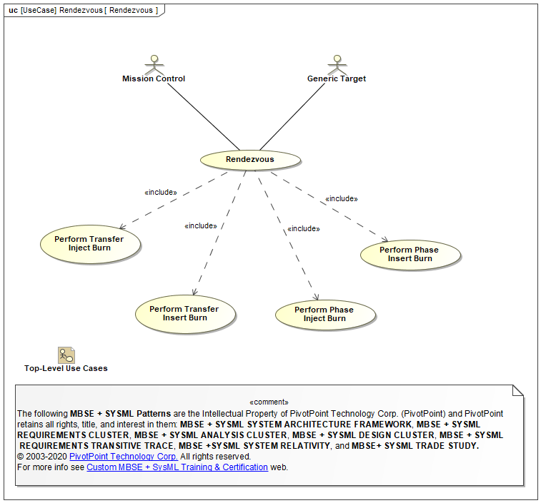
The Requirement «view» layer specifies the Functional Requirements and the Non-Functional Requirements (NFRs) of the subject System-of-interest, that must be satisfied by Unit, Integration, and System Test Cases (TCs). Requirements are typically defined on the upper "Left-Side" of the System V-Model, whereas Test Cases are typically defined on the Right-Side of the System V-Model. See Test «view» section to compare and contrast.
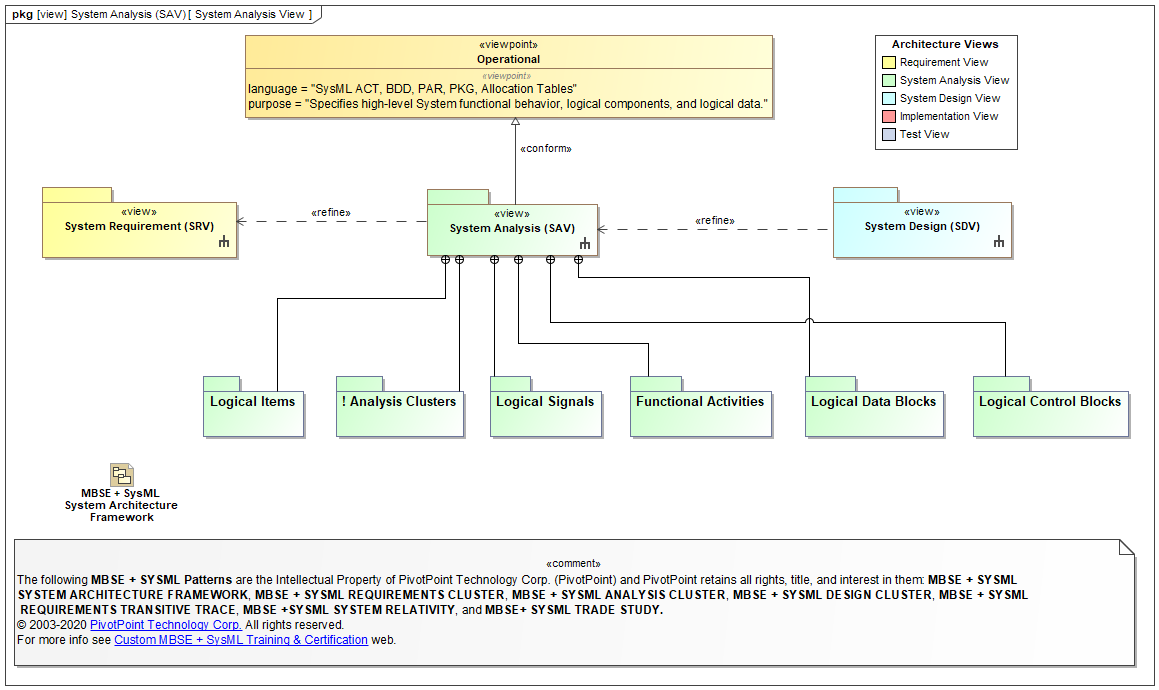
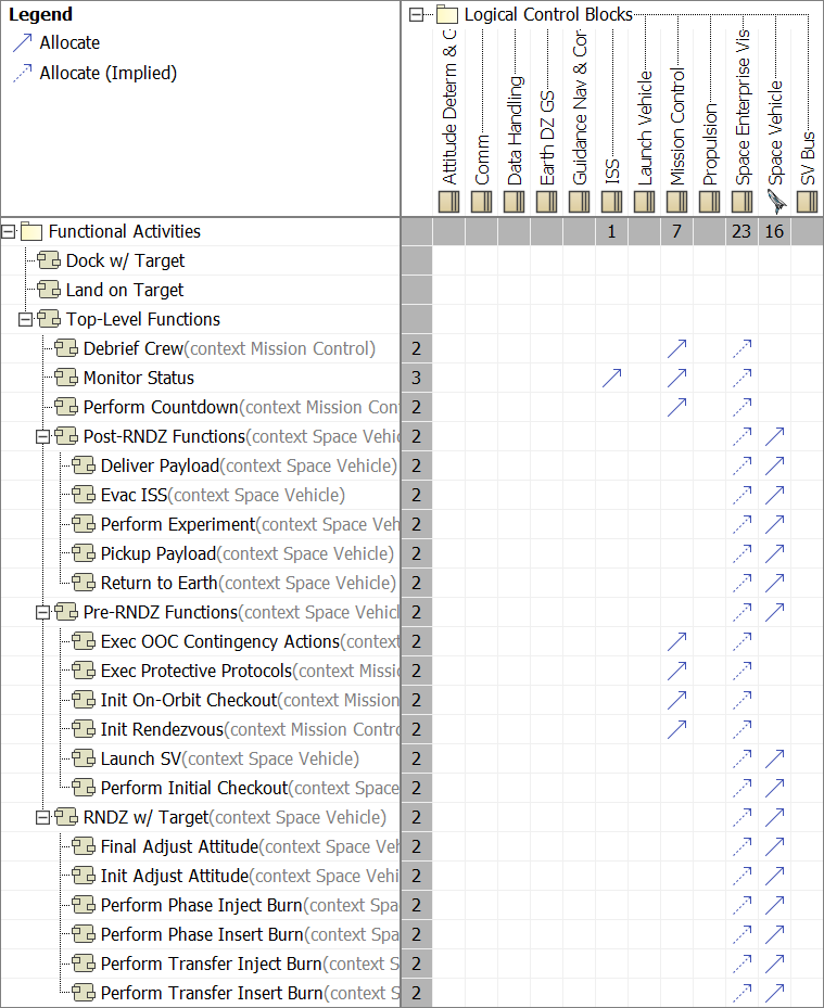
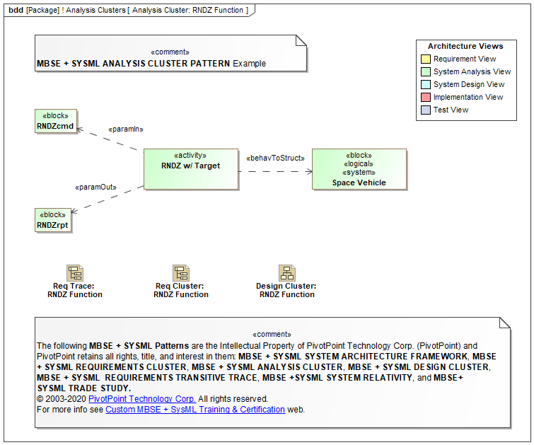
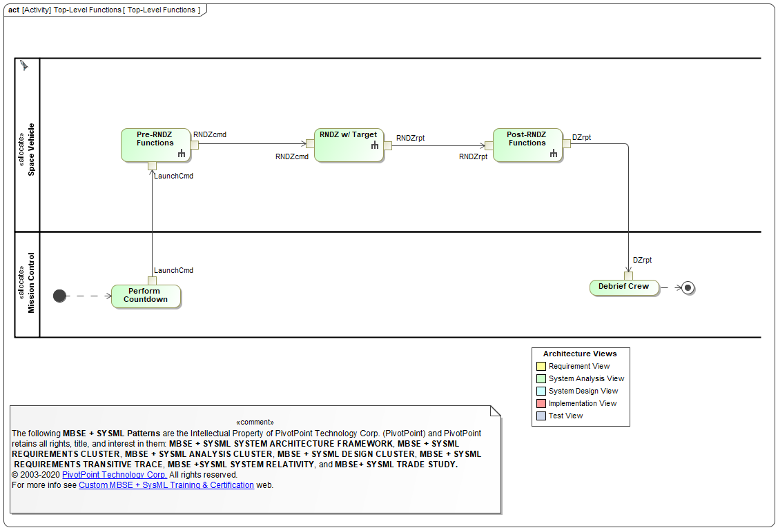
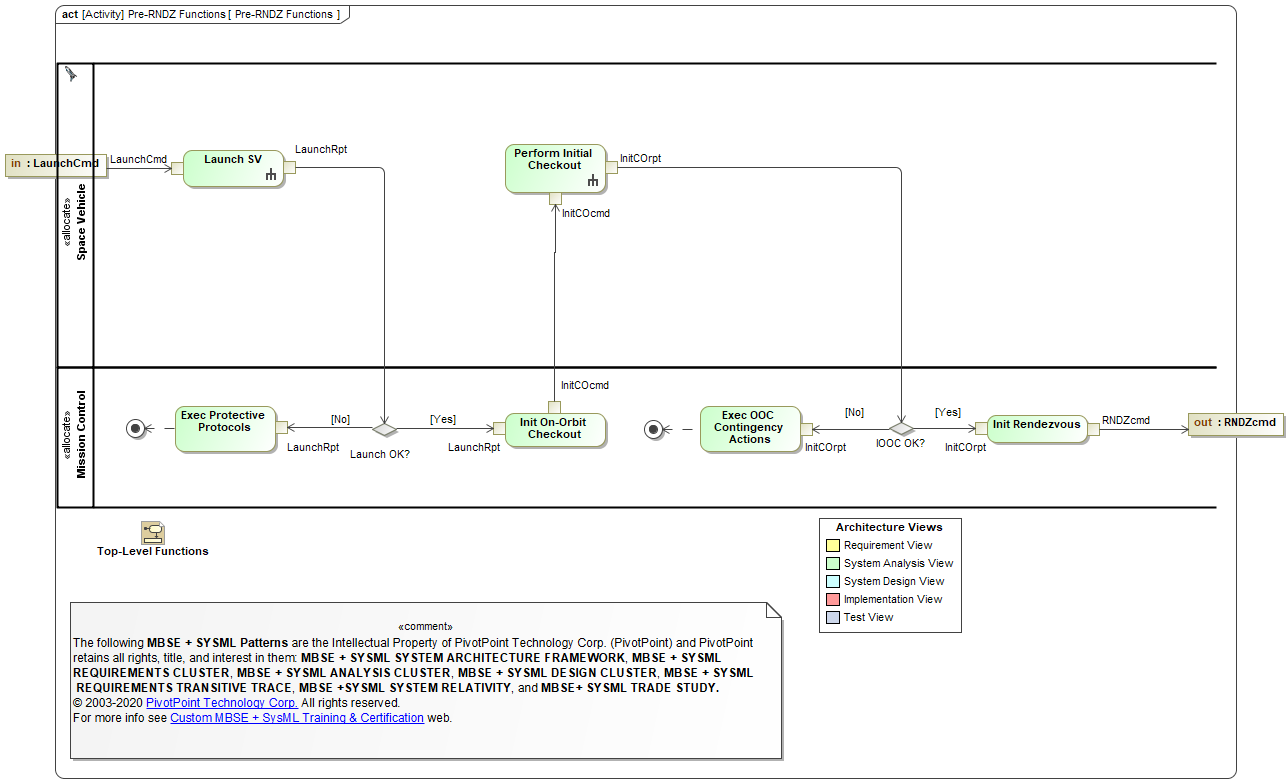
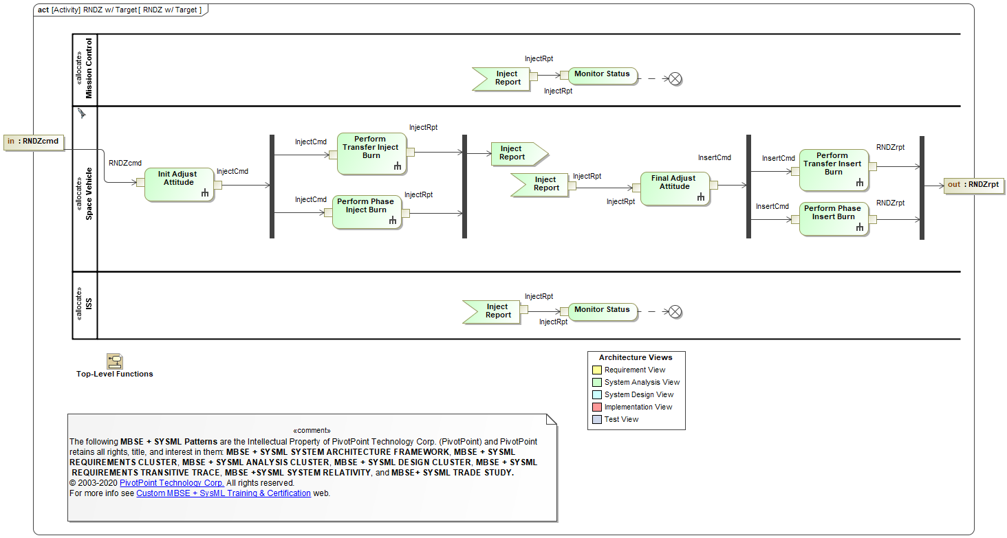
System Analysis «view»
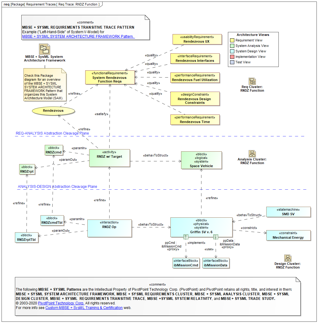
The System Analysis «view» layer specifies the high-level functions, logical components, and logical data of the subject System-of-interest. In general, the System Analysis satisfies the Requirement «view», and in turn it is refined by the System Design «view».
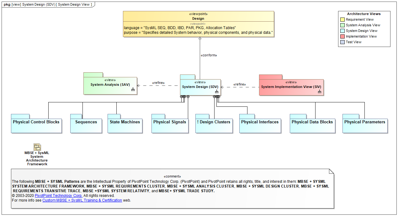
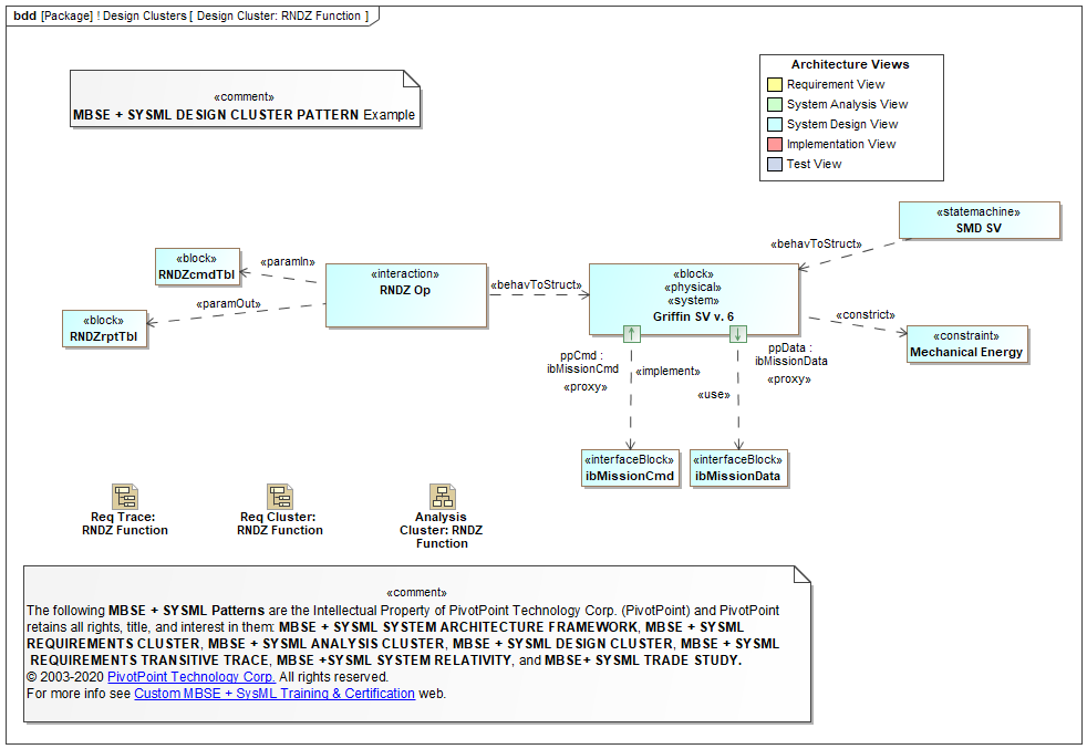
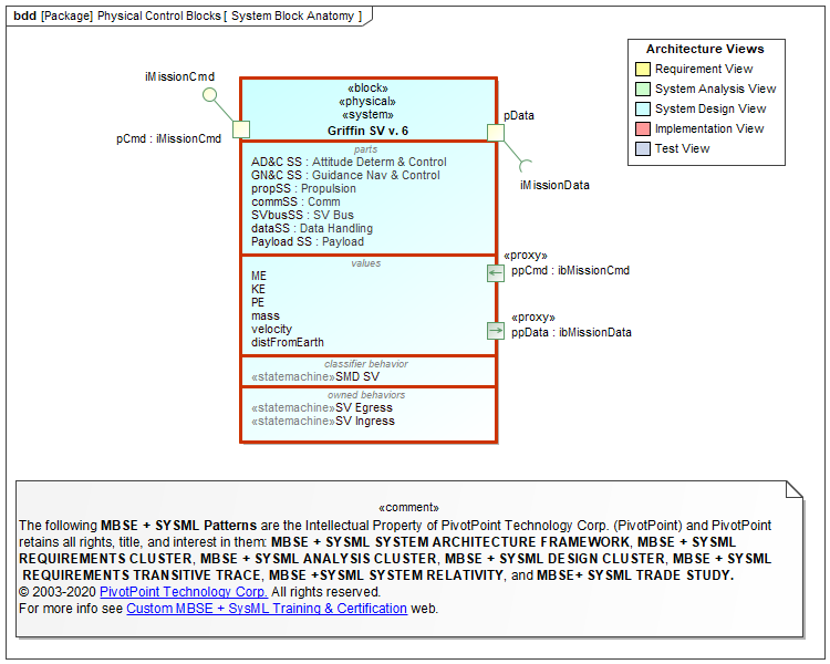
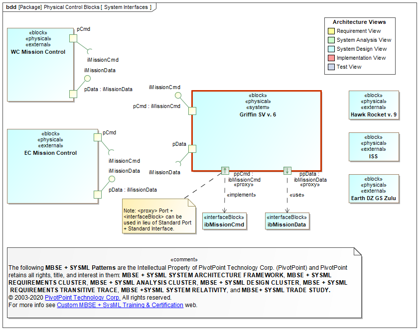
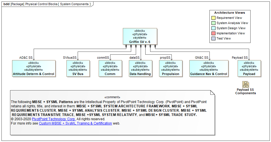
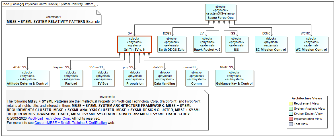
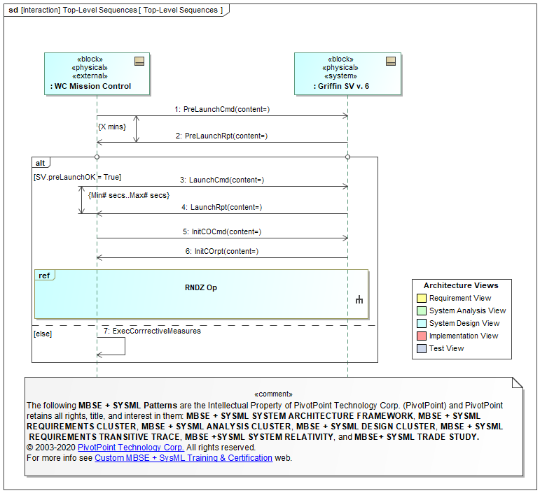
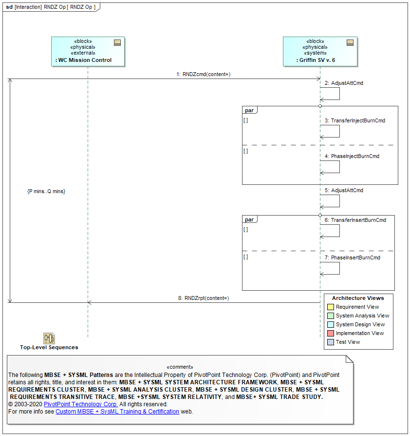
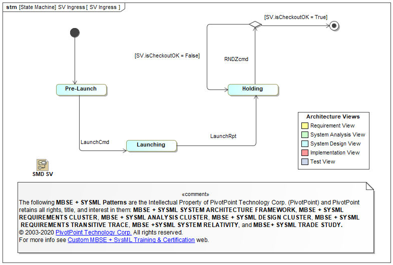
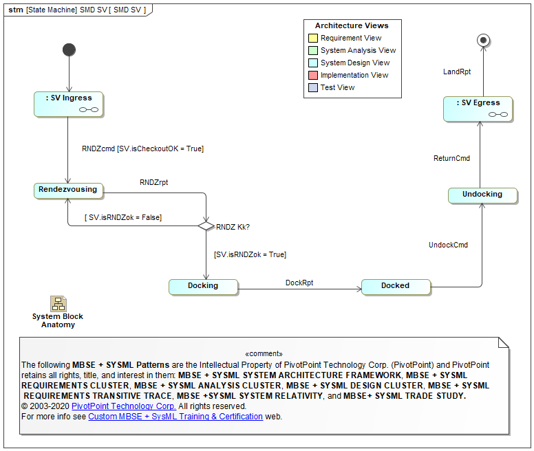
System Design «view»
The System Design «view» layer specifies the low-level (detailed) functions, physical components, and physical data of the subject System-of-interest. In general, the System Design refines the System Analysis «view», and in this manner transitive refines System Requirements traceability on the Left-Side of the System V-Model.

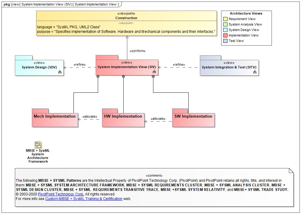
Implementation «view»
The Implementation «view» layer specifies the construction of the physical Software Components, Hardware Components, and Mechanical Components that implement the subject physical System-of-interest. In general, the Implementation & Fabrication is the "Bottom" of the traditional System V-Model: all "Left Side" System V-Model elements must trace from System Requirements to the Implementation & Fabrication components; similarly, all "Right Side" of the System V-Model Test Cases must black-box and white-box validate all Implementation & Fabication components.
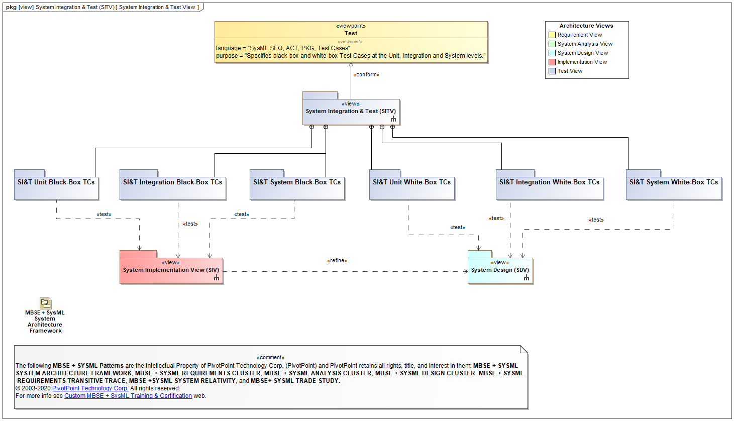
Test «view»
The Test «view» layer specifies the System Test Cases on the "Right Side" of the System V-Model that must exhaustively test the System Design and Implementation using black-box and white-box Test Cases at the Unit, Integration, and System levels.
TOGAF and ARCHIMATE are trademarks of The Open Group.
ENTERPRISE ARCHITECT is a trademark of Sparx Systems Pty Ltd. MAGICDRAW and CAMEO are trademarks of No Magic, Inc. RATIONAL RHAPSODY is a trademark of IBM.
All other trademarks are the property of their respective owners.