SysML FAQ: What is SysML? Who created SysML?
If you have constructive recommendations to correct, clarify, or otherwise improve these or any other SysML FAQs, please contact us.
General Questions
What is SysML?
Question Variant(s): What is the Systems Modeling Language?; What is OMG SysML?
Definition
Systems Modeling Language (SysML): SysML is a general-purpose system architecture modeling language for Systems Engineering applications.
- SysML supports the specification, analysis, design, verification, and validation of a broad range of systems and systems-of-systems. These systems may include hardware, software, information, processes, personnel, and facilities.
- SysML is a dialect of UML 2, and is defined as a UML 2 Profile. (A UML Profile is a UML dialect that customizes the language via three mechanisms: Stereotypes, Tagged Values, and Constraints.)
- SysML is an enabling technology for Model-Based Systems Engineering (MBSE).
The SysML was originally created by the SysML Partners' SysML Open Source Specification Project in 2003. The SysML was adapted and adopted by the Object Management Group (OMG) as OMG SysML in 2006. For more information about the current version of OMG SysML, see the SysML FAQ: What is the current version of SysML?.
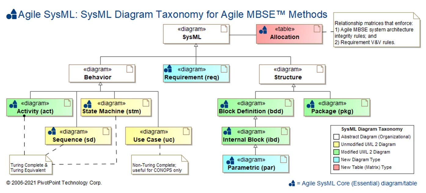
SysML Diagram Taxonomy
The SysML is composed of nine (9) diagram types and Allocation Tables for mapping language elements across diagram types:
| Diagram Name | Diagram Type | UML 2 Analog | SDLC Usage | Essential AGILE SYSML? |
Dynamic Sim † |
Math Sim ‡ |
Auto Code Gen |
Rigor | Semi | Informal |
|---|---|---|---|---|---|---|---|---|---|---|
| Requirement diagram (req) | Static Structure [Declarative] |
N/A | Requirements Analysis | |||||||
| Use Case diagram (uc) | Behavior * [Non-Simulatable] |
Use Case | Requirements Analysis | |||||||
| Activity diagram (act) | Dynamic Behavior [Simulatable] |
Activity [minor mods] |
System Analysis, Functional Analysis, System Design |
|||||||
| Sequence diagram (sd) | Dynamic Behavior [Simulatable] |
Sequence | System Design | |||||||
| State Machine diagram (stm) | Dynamic Behavior [Simulatable] |
State Machine | System Analysis, System Design |
|||||||
| Block Definition Diagram (bdd) | Static Structure [Black Box Definition] |
Class [moderate mods] |
System Analysis, System Design |
|||||||
| Internal Block Diagram (ibd) | Static Structure [White Box Usage] |
Composite Structure [moderate mods] |
System Analysis, System Design |
|||||||
| Parametric Diagram (par) | Static Structure [White Box Usage] |
N/A | System Analysis, System Design |
|||||||
| Package diagram (pkg) | Static Structure [Grouping] |
Package [minor mods] |
All SDLC phases | |||||||
| Allocation Table | N/A [Relationship Matrix] |
N/A | All SDLC phases | |||||||
†: Dynamic Simulation (a.k.a. Dynamic System Simulation) refers to the capability of a computer program to execute the time-varying behavior of a system of interest. In general, with the exception of Use Case diagrams, SysML and UML 2 Behavior diagrams are potentially capable of Dynamic System Simulation.
‡: Mathematical Modeling & Simulation (a.k.a. Mathematical ModSim, Mathematical M&S, Parametric Simulation) refers to the capability of a computer program to execute the a mathematical model of the behavior of a system of interest, where the model is defined as a set of mathematical equations. When properly defined and applied Parametric diagrams are capable of Mathematical ModSim; no other SysML or UML 2 diagrams are capable of this.
*: Although Use Case diagrams are generally classified as Behavior diagrams by both the OMG SysML and UML 2 specifications their Behavioral semantics are ambiguous and incomplete. Whereas Activity, Sequence and State Machine diagrams are Turing Complete, and their dynamic behavior can be simulated or executed, Use Cases diagrams are not Turing Complete and are not simulatable.
Who created the Systems Modeling Language (SysML)?
Question Variant(s): Who created SysML?; Who designed SysML?
The Systems Modeling Language (SysML) was developed by the SysML Partners, an informal group of Systems Engineering and software modeling tool experts led by Cris Kobryn in 2003. Their goal was to create a profile (dialect) of Unified Modeling Language v2.0 (UML 2) suitable for Systems Engineering applications.
Kobryn, who had successfully led the UML v1.x and UML v2.0 language design teams, was asked by David Oliver and Sanford Friedenthal of INCOSE in 2003 to lead their joint effort in response to the Object Management Group's UML for Systems Engineering RFP issued in March 2003. As the SysML Partners' Chair, Kobryn named the language "SysML" (short for "Systems Modeling Language"), designed the original SysML logo, and organized the SysML Language Design team as an open source specification project. Friedenthal, Chair of the OMG Systems Engineering Special Interest Group, held the position of Deputy Chair of the SysML Partners during the project's initial stages.
David Oliver, Co-Chair of the INCOSE Model Driven Design Working Group and INCOSE Fellow, advised the SysML Partners throughout the project.
The SysML Partners released the SysML v0.9 draft specification in January 2005. In August 2005, Friedenthal and some other original SysML Partners departed and formed a rival SysML Submission Team (SST). In November, the SysML Partners published the SysML v1.0 Alpha specification. This version was ultimately adopted by the OMG as OMG SysML v1.0 (Draft) in April 2006.
For further details about the history of the SysML, see the SysML Partners section of the SysML.org web.
Modeling 2007
SysML Partners: The original group of software companies that created a version of UML for systems engineering called SysML, which picked up steam in 2006. SD Times 100 Modeling 2007 Award
Why use the Systems Modeling Language (SysML)?
Question Variant(s): What is SysML used for?
If you are a Systems Engineer and want to improve the precision and efficiency of your communications with fellow Systems Engineers and other system and business stakeholders (e.g. Clients, Software Engineers, Electrical Engineers, Mechanical Engineers), then you should consider using a system Architecture Modeling Language (a.k.a. Architecture Description Language) standard as a lingua franca (common language) for your projects
The Systems Modeling Language (SysML) has emerged as the de facto standard system architecture modeling language for Model-Based Systems Engineering (MBSE) applications. SysML is a dialect of UML 2, which extends the Unified Modeling Language (UML) standard for software-intensive applications so that it can be successfully applied to Systems Engineering applications.
Here's a list of reasons why Systems Engineers may want to use SysML and a Model-Based Systems Engineering approach for their mission critical work:
- Facilitate communication among various stakeholders across the System Development Life Cycle (SDLC), including both sides of the System V-Model;
- Capture and manage corporate Intellectual Property related to system architectures, analyses, designs, and processes;
- Facilitate Trade Studies and compare and contrast “As Is” and “To Be” solutions;
- Provide scalable structure for problem solving;
- Furnish rich abstractions to manage size and complexity;
- Explore multiple solutions or ideas concurrently with minimal risk; and
- Detect errors and omissions early in System Development Life Cycle (SDLC)
Of course, like any technology SysML can be both properly applied and abused. Compare and contrast the difference between "SysML-as-Pretty-Pictures" and "SysML-as-System-Architecture-Blueprint" usage modes in the SysML FAQ: How should SysML be applied to an MBSE project? How is SysML commonly abused?.
You can find a OMG SysML v. 1.6 minor revision change summary as part of the Answer to the SysML FAQ: What is new in OMG SysML 1.6?.
As should be expected in a long (10+ years) series or minor OMG SysML 1.x minor revisions, the OMG SysML v. 1.5 minor revision includes only trivial tweaks to the language.
- Allows Requirement properties and taxonomies to be defined by specializing the SysML Requirement stereotype. Also adds Requirement compartment notation to show Requirement relationships.
- Adds Block compartment notation to show Signal Receptions.
N/A
Critical Commentary:
It's not clear why the OMG bothered with such trivial revisions to OMG SysML 1.4. The time and effort squandered would be better spent accelerating the long overdue OMG SysML 2.0 revision process.
Download:
You can download the OMG SysML v. 1.5 specification, as well as specifications for previous versions, from the SysML Specifications page.
What are the SysML diagram types?
Question Variant(s): How do the SysML diagrams compare and contrast?; What are SysML Allocation Tables and what are they used for?
The SysML is composed of nine (9) diagram types and Allocation Tables for mapping language elements across diagram types:
- Requirement diagram (req)
- Structure Diagrams
- Behavior Diagrams
- Allocation Table
The SysML Diagram Taxonomy comparison table below explains the similaries and differences among the various SysML diagram types.
SysML Diagram Taxonomy
The SysML is composed of nine (9) diagram types and Allocation Tables for mapping language elements across diagram types:
| Diagram Name | Diagram Type | UML 2 Analog | SDLC Usage | Essential AGILE SYSML? |
Dynamic Sim † |
Math Sim ‡ |
Auto Code Gen |
Rigor | Semi | Informal |
|---|---|---|---|---|---|---|---|---|---|---|
| Requirement diagram (req) | Static Structure [Declarative] |
N/A | Requirements Analysis | |||||||
| Use Case diagram (uc) | Behavior * [Non-Simulatable] |
Use Case | Requirements Analysis | |||||||
| Activity diagram (act) | Dynamic Behavior [Simulatable] |
Activity [minor mods] |
System Analysis, Functional Analysis, System Design |
|||||||
| Sequence diagram (sd) | Dynamic Behavior [Simulatable] |
Sequence | System Design | |||||||
| State Machine diagram (stm) | Dynamic Behavior [Simulatable] |
State Machine | System Analysis, System Design |
|||||||
| Block Definition Diagram (bdd) | Static Structure [Black Box Definition] |
Class [moderate mods] |
System Analysis, System Design |
|||||||
| Internal Block Diagram (ibd) | Static Structure [White Box Usage] |
Composite Structure [moderate mods] |
System Analysis, System Design |
|||||||
| Parametric Diagram (par) | Static Structure [White Box Usage] |
N/A | System Analysis, System Design |
|||||||
| Package diagram (pkg) | Static Structure [Grouping] |
Package [minor mods] |
All SDLC phases | |||||||
| Allocation Table | N/A [Relationship Matrix] |
N/A | All SDLC phases | |||||||
†: Dynamic Simulation (a.k.a. Dynamic System Simulation) refers to the capability of a computer program to execute the time-varying behavior of a system of interest. In general, with the exception of Use Case diagrams, SysML and UML 2 Behavior diagrams are potentially capable of Dynamic System Simulation.
‡: Mathematical Modeling & Simulation (a.k.a. Mathematical ModSim, Mathematical M&S, Parametric Simulation) refers to the capability of a computer program to execute the a mathematical model of the behavior of a system of interest, where the model is defined as a set of mathematical equations. When properly defined and applied Parametric diagrams are capable of Mathematical ModSim; no other SysML or UML 2 diagrams are capable of this.
*: Although Use Case diagrams are generally classified as Behavior diagrams by both the OMG SysML and UML 2 specifications their Behavioral semantics are ambiguous and incomplete. Whereas Activity, Sequence and State Machine diagrams are Turing Complete, and their dynamic behavior can be simulated or executed, Use Cases diagrams are not Turing Complete and are not simulatable.
(What are the essential diagrams of SysML?)
Contrary to MBSE and tool-vendor Muddle-Driven Marketecture hype, the differences between the SysML and UML modeling languages are more lightweight and dialectical in nature than heavyweight and substantive. This should be expected since SysML was originally designed to be used by Systems Engineers collaborating with Software Engineers applying UML for software analysis and design, and SysML is defined as a modestly extended pragmatic subset of UML 2. (See SysML FAQ: Can SysML and UML model elements be combined in the same model?)
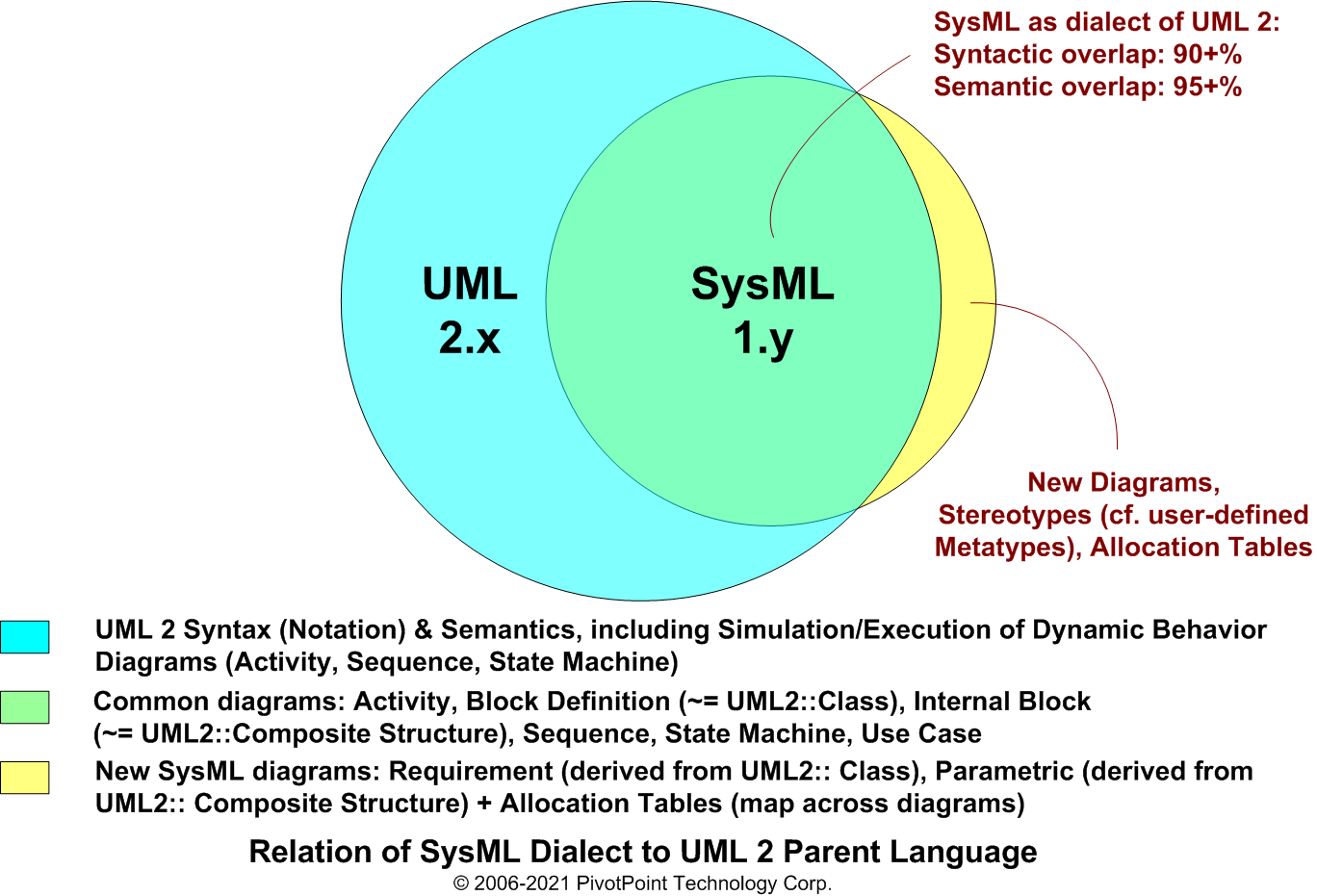
SysML is defined as a lightweight dialect (Profile) of UML 2.x, the industry standard modeling language for software-intensive applications. (The SysML Profile is lightweight in the sense that the changes that it makes to the underlying language are relatively modest in scope and extent, using a small number of simple stereotypes, tagged values and constraints. Compare and contrast with a heavyweight Profile, which could significantly impact how the underlying language is used.) The advantage of defining SysML as a UML Profile is that it can reuse the relatively mature notation and semantics of UML 2.x, which many modeling tool vendors have already implemented. The disadvantage of specifying SysML as a UML Profile is that SysML inherits many of the problems associated with UML 2.x, such as gratuitously complex notation, imprecise semantics, and a dysfunctional diagram interoperability standard (XMI).
• SysML expresses systems engineering semantics (interpretations of notations) better than than UML. It reduces UML's software bias and adds two new diagram types for requirements management and performance analysis: Requirement diagrams and Parametric diagrams, respectively.
• SysML is smaller and easier to learn than UML. Since SysML removes many software-centric and gratuitous constructs, the overall language is smaller as measured in diagram types (9 vs. 13) and total constructs.
• SysML model management constructs support the specification of models, views, and viewpoints that are architecturally aligned with IEEE-Std-1471-2000 (IEEE Recommended Practice for Architectural Description of Software-Intensive Systems).
SYSML DIAGRAM
PURPOSE
UML DIAGRAM ANALOG
Useful for functional analysis.
Compare Flow Block Diagrams (FBDs) and Extended Functional Flow Block diagrams (EFFBDs), already commonly used among systems engineers.
Activity diagram
Useful for system analysis and design.
Class diagram
Useful for system analysis and design.
Composite Structure diagram
Useful for model management.
Package diagram
Useful for requirements engineering, including requirements verification and validation (V&V).
Useful for system analysis and design.
Sequence diagram
Useful for system design and simulation/code generation.
State Machine diagram
Useful for specifying functional requirements. (Note potential semantic overlap with functional Requirements specified in Requirement diagrams.)
Use Case diagram
Useful for facilitating automated verification and validation (V&V) and gap analysis.
Object diagram
Communication diagram
Component diagram
Deployment diagram
Interaction Overview diagram
Profile diagram
Timing diagram
What is Model-Based Systems Engineering (MBSE) and how is it used?
Question Variant(s): What is MBSE?; What is Model-Based Systems Development (MBSD)?; What is Agile MBSE?
Model-Based Systems Engineering (MBSE), a.k.a. Model-Based Systems Development (MBSD), is a Systems Engineering process paradigm that emphasizes the application of rigorous architecture modeling principles and best practices to Systems Engineering activities throughout the System Development Life Cycle (SDLC). These Systems Engineering activities include, but are not limited to, requirements analysis, system (functional) analysis, performance analysis (trade studies), system design, system architecture specification, and system Verification & Validation (V&V).
According to the INCOSE SEBoK (Systems Engineering Book of Knowledge) MBSE may be considered a "subset of digital engineering".
MBSE Best Practices
It is essential that a Model-Based Systems Engineering (MBSE) approach strive to meet or exceed achieve the following process goals:
- Architecture-centric: The MBSE process must emphasize a precise and complete System Architecture Model (SAM) "blueprint", typically organized using an Architecture Framework (e.g., ISO/IEC 42010, DoDAF, TOGAF) with multiple Views/Viewpoints, as the primary work artifact throughout the System Development Life Cycle (SDLC);
- Requirements-driven: All System Analysis, System Design, and Implementation elements on the "Left Side" of the System V-Model must directly or indirectly trace to System Functional and Non-Functional Requirements.
- Test-driven: All System Test Cases on the "Right Side" of the System V-Model must exhaustively test the System Design and Implementation using black-box and white-box Test Cases at the Unit, Integration, and System levels.
- Support full SDLC with rigorous V&V: The MBSE process must provide comprehensive support of all SDLC phases (Requirements, System Analysis, System Design, Implementation, System Integration, Testing), including rigorous Verification & Validation (V&V);
- Scalable: The MBSE Process must scale recursively to accommodate Systems-of-Systems of arbitrary complexity;
- Simulatable: The MBSE process must be capable must be capable of Dynamic Simulation (a.k.a. Dynamic System Simulation) of all SysML Behavior diagrams (Activities, Sequences, State Machines) and Mathematical Modeling & Simulation (a.k.a. Mathematical ModSim, Mathematical M&S, Parametric Simulation) of all Parametric diagrams;
- Integrate SE & Agile Engineering best practices: The MBSE process must be capable of enhancing traditional Systems Engineering best practices with Model-Based improvements and integrating them with Agile Engineering best practices = Agile MBSE.
In addition, it is desirable that a MBSE approach achieve the following process goals:
- Straightforward & systematic: The MBSE process should be explained in a straightforward and systematic manner, so that it is easy for Systems Engineers to learn and apply.
- Promote the use of open standards: The MBSE process should support open standards for system architecture modeling and tool interoperability. These open standards include, but are not limited to SysML, UML 2, XMI, and AP233. These open standards should be used to specify the System Architecture Model and to serve as a lingua franca among Systems Engineers and other stakeholders (Software Engineers, Electrical Engineers, Mechanical Engineers, Customers, etc.).
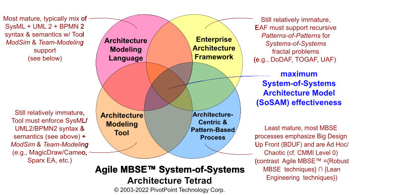
Bitter experience has show that MBSE projects that fail to properly balance the four parts of the System Architecture Tetrad tend to achieve poor or mixed results.
For a longer and more thorough explanation of the relationships among Model-Based Systems Engineering, Model-Based Engineering, and related MBE subdisciplines check out the Model-Based Engineering Forum and the Model-Based Engineering Visual Glossary.
In theory SysML and UML model elements can be synergistically combined in the same model. Indeed, this was one of the language design goals of the SysML Partners' open source specification project:
• Support SysML + UML mixed language usage:
Ensure that SysML constructs can be synergistically combined with UML constructs in a model shared by Systems Engineers and Software Engineers, where the former use SysML and the latter use UML. The synergistic combination of SysML and UML should maximize requirements traceability and minimize semantic overlap between the two languages. “SysML Language Design Goals”, SysML Partners
In practice, unfortunately, users frequently find it confusing and problematic to combine SysML and UML model elements in the same model, just as they find it befuddling and vexing to interchange SysML and UML models across supposedly XMI (XML Model Interchange) compliant modeling tools. It appears that the Object Management Group (OMG) is following a "family of languages" visual modeling design philosophy, as opposed to the "unification of languages" design philosophy that dominated UML 1.x adoption and revisions during the late 1990's and early 2000's. This misguided and poorly executed design philosophy has resulted in a "Tower of Techno-Babble" anti-pattern for users who want to synergistically combine the OMG's most popular visual modeling languages (UML, SysML, BPMN), and it has resulted in a "Meta-Babble" anti-pattern for vendors relying on the gratuitously complex Meta Object Facility (MOF) and XMI for reliable model interchange.
So, given the "Tower of Techno-Babble" anti-pattern described above, how can a team comprised of both Systems Engineers and Software Engineers specify a model that harmoniously combines SysML and UML model elements? The following outlines a technical approach based on the transitivity of requirements traceability dependencies (notably «satisfy» and «refine»), that has proven effective on numerous large, mixed modeling language projects:
Select a UML modeling tool that correctly implements SysML as a UML2 compliant profile and allows you to populate SysML diagrams with UML constructs and populate UML diagrams with SysML constructs:
UML modeling tools that support SysML vary widely in this regard, with some being more restrictive than others since the OMG specifications generally defer this sort of implementation detail to vendors. Check out SysMLtools.com for candidate SysML modeling tools that support SysML + UML2 mixed language usage.- Organize your model into well-defined Views along the lines of the following, where UML and SysML diagrams are combined in a complementary manner:
(See SysML «view» stereotype of Package for View notation and semantics.) Modelers should feel free to modify the following Views and their contents consistent with their chosen Model-Based Systems Engineering (MBSE) and/or Model-Driven Development (MDD) methods.- Requirements «view»: Systems Engineers are primarily responsible for the completeness, correctness, and integrity of this View and the definition of its corresponding Viewpoint. Candidate diagram type contents include, but are not limited to, the following: UML/SysML Use Case and SysML Requirement diagrams.
- System Analysis or Functional Analysis «view»: Systems Engineers are primarily responsible for the completeness, correctness, and integrity of this View and the definition of its corresponding Viewpoint. Candidate diagram type contents include, but are not limited to, the following: SysML Block Definition, Internal Block, Parametric, Activity, and State Machine diagrams. Other SysML diagrams may be added as needed.
- System Design «view»: Software Engineers are primarily responsible for the completeness, correctness, and integrity of this View and the definition of its corresponding Viewpoint. Candidate diagram type contents include, but are not limited to, the following: UML Class, Composite Structure, Sequence, Timing, State Machine, Component, and Deployment diagrams.
- ...other Views as needed for Implementation, Testing, etc.
- Ensure bi-directional Requirements Traceability on both sides of the System V-Model:
The modeling team should designate and consistently apply appropriate dependencies for full requirements traceability across all Views. You can synergistically effect full traceability across the complementary Views described above by applying the following traceability dependency patterns within and across Views:- Traceablity within the Requirements «view»: Define Refine («refine») dependencies between functional Requirements and the Use Cases that refine them.
- Traceability between the Requirements «view» & System Analysis «view»: Define Satisfy («satisfy») dependencies between Requirements and the Activities and Blocks that satisfy them. (Optional: As per common UML best practice, you can also define a Realization or Refine dependency between a Use Case and any Activity that realizes or refines it.)
- Traceability between the System Analysis «view» & System Design «view»: Define Refine dependencies between the SysML Blocks and Activities defined in the System Analysis «view» and the UML Classes and Sequences that refine them in the System Design «view».
- Traceability across other Views: Since Refine is a transitive relationship, System Design «view» model elements can be further refined and traced across other Views (e.g., Implementation/Construction, Deployment, Testing, etc.).
Combined SysML + UML2 Example Request: If you are interested in pursuing the technical approach outlined above, but need a combined SysML + UML2 example to better understand how it works, please contact us. If we receive sufficient requests for a combined SysML + UML2 example (say 10+ requests), we will post one to the SysML Forum.
SYSML & UML 2 GENERAL ISSUES (Shared with UML 2.x parent language)
Language bloat:
A common and fair criticism of UML 2.x is that it is gratuitously large and complex. While SysML marketecture indicates that SysML is a "smaller, simpler" language for systems engineers, the reality is that SysML itself also suffers from language bloat because it adds two new diagrams (Requirements and Parametrics) and substantially increases the number of stereotypes with imprecise semantics (see Increase of UML 2.x voodoo semantics below), while failing to explicitly exclude many redundant and software-centric UML 2 constructs from the seven UML 2 diagrams that it inherits. The bloat is exacerbated because the SysML specification provides no guidelines regarding how to combine SysML models with UML models for engineering teams that include both software engineers and system engineers.
- Recommendations: Explicitly remove UML constructs not needed for SysML. Provide concrete guidelines regarding how to combine SysML models with UML models for engineering teams that include both software engineers and system engineers. Encourage tool vendors to support automated translation of diagrams shared between the two languages.
Increase of UML 2.x voodoo semantics:
Another common and fair criticism of UML 2.x is that its semantics, including its purported executable semantics (a.k.a. the Action Semantics) are ambiguous and imprecise. While SysML marketecture indicates that SysML supports precise semantics for specifying parametric constraints, the reality is SysML defines only vague natural language semantics for ConstraintBlock, ConstraintProperty, and Context-Specific Values/Constraints. Similarly, the semantics for Activity diagram extensions related to continuous/discrete rates and probabilities lack formal precision.
- Recommendations: Add precise semantics for Parametric and Requirement diagram constructs, and Activity diagram extensions.
SYSML-SPECIFIC ISSUES (Apply to SysML but not UML 2 parent language)
Structural constructs for Physical and Information (Standard) Interfaces are gratuitously complex and confusing:
The semantics and notations for StandardPorts, FlowPorts, Provided & Required Interfaces, and ItemFlows were gratuitously complex and confusing in SysML v. 1.0 - 1.2 since they conflated dependency relationships with flow relationships. Unfortunately, the patches made to fix these problems with new constructs in the SysML v. 1.3 minor revision (FullPorts, ProxyPorts, InterfaceBlocks) have exacerbated these problems, rather than fix them.
Although Instance Specifications were recently added to SysML 1.2, Object diagrams were not, and many issues remain about their specialized usage within SysML.
- Recommendations: Unify, simplify, and clarify the Physical and Information Interface syntax and semantics in the next major revision, SysML 2.0.
Instance Specifications are ambiguously defined and poorly integrated with the rest of SysML:
Although Instance Specifications were recently added to SysML 1.2, Object diagrams are clearly an afterthought in the language, and have never been fully integrated with the rest of SysML.
- Recommendations: Add Object diagrams as a first-class SysML diagram type, and clarify the similarities and differences between SysML and UML Instance Specification syntax, semantics, and usages.
Parametric constructs are ambiguously defined and poorly integrated with the rest of SysML:
Parametric Constraint Blocks and Constraint Properties are ambiguously defined and poorly integrated with other SysML structural diagrams. They currently have the dubious distinction of being the least mature and most problematic SysML diagram to use.
- Recommendations: Parametric Diagrams need a complete overhaul in the next SysML major revision (SysML 2.0). This overhaul should factor in lessons learned from building bi-directional bridges between SysML 1.x Parametric diagrams and 3rd party mathematical modeling & simulation tools (e.g., MATLAB/Simulink, Mathematica).
Requirement constructs are incomplete and confusing:
Problems associated with Requirement diagrams include, but are not limited to, clarifying decomposition/containment semantics, categorization, defining basic properties, clarifying relationship semantics, and reducing the semantic overlap with Use Cases.
- Recommendations: Replace Containment with Composition for Requirements decomposition. Retire Copy dependency. Provide additional Requirement properties for source, priority, risk, verifyMethod, etc.
Allocation relationships and tables are incomplete and ambiguous:
With the exception of the AllocateActivityPartition stereotype the current specification fails to leverage the architectural integrity allocations of its parent language. In addition, the definitions of the Allocate and Allocated stereotypes strongly suggest conflated dependency and flow semantics, which are indicative of novice UML modelers ("which way does the arrow point?").
- Recommendations: Replace Allocate dependencies with flows that use distinctive notation (not dashed arrows labeled with keywords). Require that implementations automatically generate Allocate dependencies for AllocateActivityPartitions.
ValueType-Type integration needs simplification and a SI Model Library:
The current usage of ValueTypes with Units and QuantityKinds (formerly Dimensions) and their integration with UML DataTypes needs to be clarified and simplified.
- Recommendations: Simplify and predefine a standard SysML ValueType model library based on International System of Units (SI) standards.
In order to increase your likelihood of achieving SysML language fluency, you may want to consider a multi-pronged approach to learning SysML. For example, if you have the opportunity you may want to start off with basic SysML hands-on training, followed up by expert coaching (mentoring) for On The Job training, which in turn is followed up with advanced SysML hands-on training. For the best learning experience, ensure that all your SysML training is taught by expert practitioners with extensive application experience on large projects, and includes frequent hands-on practice sessions and Q&A sessions.
In addition, you should also also read voraciously about SysML techniques and best practices, so that you can further benefit from the experience (and mistakes) of others.
You can find a listing of selected SysML training resources on the SysML Training page of this web.
You can find a listing of selected SysML tutorials on the SysML Tutorials page of this web.
You can find a listing of selected SysML publications (including books, papers, and articles) on the SysML Publications page of this web.
Why is SysML an attractive alternative to UML? Consider that SysML is substantially smaller than UML 2.x, so it is easier to learn and apply, yet it is more semantically expressive than UML 2.x, so you can specify visual Requirements and Parametric Constraints as well as Analysis and Design artifacts. Stated otherwise, SysML is more agile and more semantically powerful, while UML is plodding and less semantically powerful. So it shouldn't be surprising that many software engineers and developers are looking at SysML as a "better UML."
How can I report a SysML issue or make a SysML change request?
You can comment on any open issue by sending email to sysml-rtf@omg.org. In addition you can submit new issues, including change requests, by sending email to issues@omg.org.
SysML Diagrams & Modeling Techniques
What are the SysML diagram types?
Question Variant(s): How do the SysML diagrams compare and contrast?; What are SysML Allocation Tables and what are they used for?
The SysML is composed of nine (9) diagram types and Allocation Tables for mapping language elements across diagram types:
- Requirement diagram (req)
- Structure Diagrams
- Behavior Diagrams
- Allocation Table
The SysML Diagram Taxonomy comparison table below explains the similaries and differences among the various SysML diagram types.
SysML Diagram Taxonomy
The SysML is composed of nine (9) diagram types and Allocation Tables for mapping language elements across diagram types:
| Diagram Name | Diagram Type | UML 2 Analog | SDLC Usage | Essential AGILE SYSML? |
Dynamic Sim † |
Math Sim ‡ |
Auto Code Gen |
Rigor | Semi | Informal |
|---|---|---|---|---|---|---|---|---|---|---|
| Requirement diagram (req) | Static Structure [Declarative] |
N/A | Requirements Analysis | |||||||
| Use Case diagram (uc) | Behavior * [Non-Simulatable] |
Use Case | Requirements Analysis | |||||||
| Activity diagram (act) | Dynamic Behavior [Simulatable] |
Activity [minor mods] |
System Analysis, Functional Analysis, System Design |
|||||||
| Sequence diagram (sd) | Dynamic Behavior [Simulatable] |
Sequence | System Design | |||||||
| State Machine diagram (stm) | Dynamic Behavior [Simulatable] |
State Machine | System Analysis, System Design |
|||||||
| Block Definition Diagram (bdd) | Static Structure [Black Box Definition] |
Class [moderate mods] |
System Analysis, System Design |
|||||||
| Internal Block Diagram (ibd) | Static Structure [White Box Usage] |
Composite Structure [moderate mods] |
System Analysis, System Design |
|||||||
| Parametric Diagram (par) | Static Structure [White Box Usage] |
N/A | System Analysis, System Design |
|||||||
| Package diagram (pkg) | Static Structure [Grouping] |
Package [minor mods] |
All SDLC phases | |||||||
| Allocation Table | N/A [Relationship Matrix] |
N/A | All SDLC phases | |||||||
†: Dynamic Simulation (a.k.a. Dynamic System Simulation) refers to the capability of a computer program to execute the time-varying behavior of a system of interest. In general, with the exception of Use Case diagrams, SysML and UML 2 Behavior diagrams are potentially capable of Dynamic System Simulation.
‡: Mathematical Modeling & Simulation (a.k.a. Mathematical ModSim, Mathematical M&S, Parametric Simulation) refers to the capability of a computer program to execute the a mathematical model of the behavior of a system of interest, where the model is defined as a set of mathematical equations. When properly defined and applied Parametric diagrams are capable of Mathematical ModSim; no other SysML or UML 2 diagrams are capable of this.
*: Although Use Case diagrams are generally classified as Behavior diagrams by both the OMG SysML and UML 2 specifications their Behavioral semantics are ambiguous and incomplete. Whereas Activity, Sequence and State Machine diagrams are Turing Complete, and their dynamic behavior can be simulated or executed, Use Cases diagrams are not Turing Complete and are not simulatable.
SysML Diagram Taxonomy
The SysML is composed of nine (9) diagram types and Allocation Tables for mapping language elements across diagram types:
| Diagram Name | Diagram Type | UML 2 Analog | SDLC Usage | Essential AGILE SYSML? |
Dynamic Sim † |
Math Sim ‡ |
Auto Code Gen |
Rigor | Semi | Informal |
|---|---|---|---|---|---|---|---|---|---|---|
| Requirement diagram (req) | Static Structure [Declarative] |
N/A | Requirements Analysis | |||||||
| Use Case diagram (uc) | Behavior * [Non-Simulatable] |
Use Case | Requirements Analysis | |||||||
| Activity diagram (act) | Dynamic Behavior [Simulatable] |
Activity [minor mods] |
System Analysis, Functional Analysis, System Design |
|||||||
| Sequence diagram (sd) | Dynamic Behavior [Simulatable] |
Sequence | System Design | |||||||
| State Machine diagram (stm) | Dynamic Behavior [Simulatable] |
State Machine | System Analysis, System Design |
|||||||
| Block Definition Diagram (bdd) | Static Structure [Black Box Definition] |
Class [moderate mods] |
System Analysis, System Design |
|||||||
| Internal Block Diagram (ibd) | Static Structure [White Box Usage] |
Composite Structure [moderate mods] |
System Analysis, System Design |
|||||||
| Parametric Diagram (par) | Static Structure [White Box Usage] |
N/A | System Analysis, System Design |
|||||||
| Package diagram (pkg) | Static Structure [Grouping] |
Package [minor mods] |
All SDLC phases | |||||||
| Allocation Table | N/A [Relationship Matrix] |
N/A | All SDLC phases | |||||||
†: Dynamic Simulation (a.k.a. Dynamic System Simulation) refers to the capability of a computer program to execute the time-varying behavior of a system of interest. In general, with the exception of Use Case diagrams, SysML and UML 2 Behavior diagrams are potentially capable of Dynamic System Simulation.
‡: Mathematical Modeling & Simulation (a.k.a. Mathematical ModSim, Mathematical M&S, Parametric Simulation) refers to the capability of a computer program to execute the a mathematical model of the behavior of a system of interest, where the model is defined as a set of mathematical equations. When properly defined and applied Parametric diagrams are capable of Mathematical ModSim; no other SysML or UML 2 diagrams are capable of this.
*: Although Use Case diagrams are generally classified as Behavior diagrams by both the OMG SysML and UML 2 specifications their Behavioral semantics are ambiguous and incomplete. Whereas Activity, Sequence and State Machine diagrams are Turing Complete, and their dynamic behavior can be simulated or executed, Use Cases diagrams are not Turing Complete and are not simulatable.
What is a SysML Requirement diagram?
Definitions
Requirement: A Requirement (notation: rectangle with «requirement» keyword) is a capability or condition that a system must ("shall") satisfy. A Functional Requirement (functionalRequirement» keyword) specifies a function that a system must perform, whereas a Non-Functional Requirement (NFR) specifies quality criteria that can be used to test the effectiveness of system functions.
SysML predefines the following stereotype specializations of NFRs:
- «performanceRequirement»
- «interfaceRequirement»
- «designConstraint»
- «physicalRequirement»
Requirement diagram (req): A SysML Requirement diagram is a static structural diagram that shows the relationships among Requirement («requirement») constructs, model elements that Satisfy («satisfy» Dependency) them, and Test Cases that Verify («verify» Dependency) them.
Purpose
The purpose of Requirement diagrams is to specify both Functional and Non-Functional Requirements within the model so that they can be traced to other model elements that Satisfy them and Test Cases that Verify them.
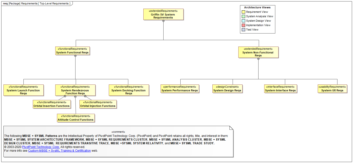
Top-Level Requirements
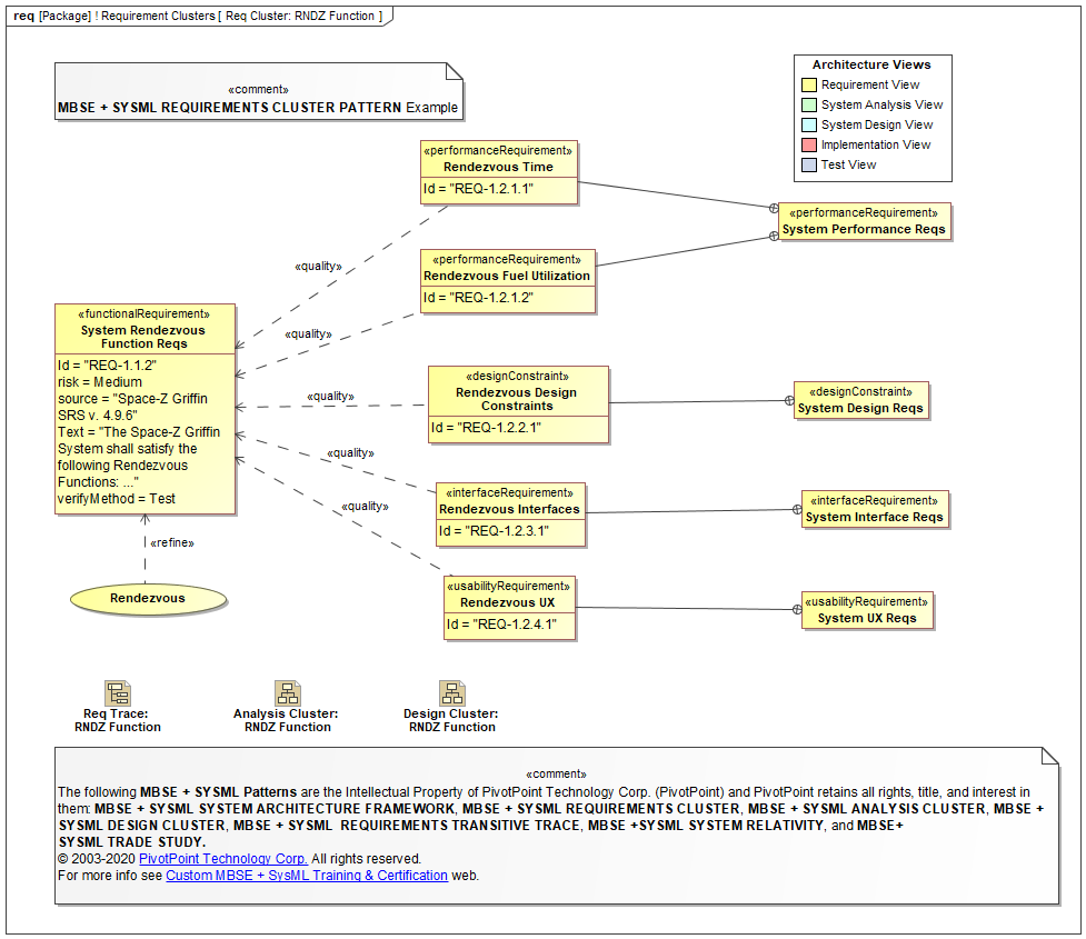
Requirements Cluster Pattern
Diagram Properties
| Diagram Name | Diagram Type | UML 2 Analog | SDLC Usage | Essential AGILE SYSML? |
Dynamic Sim † |
Math Sim ‡ |
Auto Code Gen |
Rigor | Semi | Informal |
|---|---|---|---|---|---|---|---|---|---|---|
| Requirement diagram (req) | Static Structure [Declarative] |
N/A | Requirements Analysis | |||||||
Usage Notes
| BEST PRACTICE PATTERNS | ANTI-PATTERNS |
|---|---|
| * Aggressively apply Requirements Triage techniques to separate «functionalRequirement», «performanceRequirement», and «designConstraint» Requirements. | * Conflate «functionalRequirement», «performanceRequirement», and «designConstraint» Requirements. |
| * Satisfy all Functional Requirements with Functional Activities using the «satisfy» Dependency. | * Regurgitate System Design decisions as SysML Requirements text. Compare and contrast bona fide «designConstraint» Requirements (e.g., "... shall use FOSS SW and COTS HW ..."). |
| * Apply MBSE + SysML Requirements Cluster Pattern to manage FR-NFR complexity. | |
| * Apply MBSE + SysML Requirements Transitive Trace Pattern to scale system Requirements traceability on the "Left-Hand-Side" of the System V-Model. |
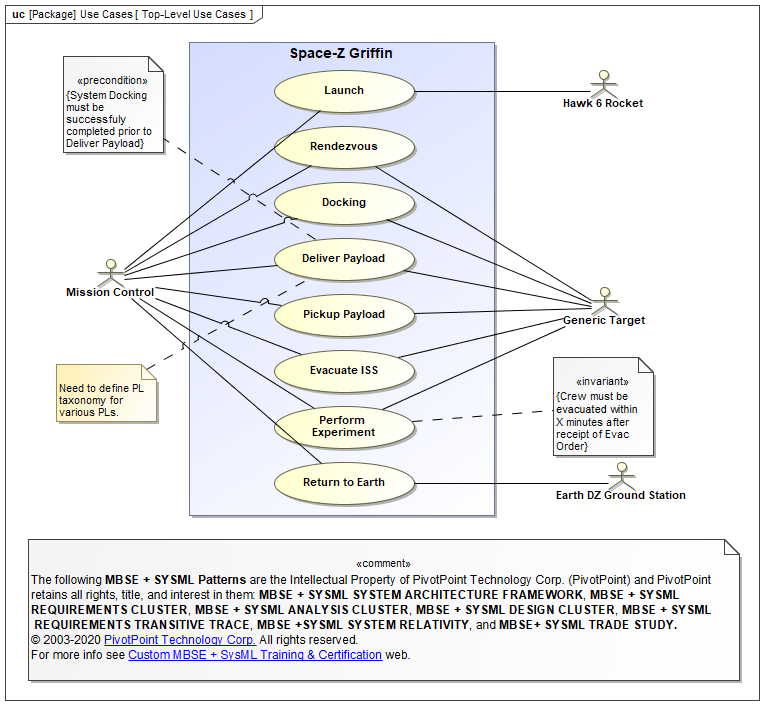
What is a SysML Use Case diagram?
Definitions
Use Case: A Use Case (notation: oval/ellipse) represents a system transaction with an external system user, called an Actor (notation: stick-figure). Use Cases are sometimes considered high-level functional requirements.
Use Case diagram (uc): A Use Case diagram shows communications among system transactions (Use Cases) and external users (Actors) in the context of a system boundary (Subject; notation: rectangle). Actors may represent wetware (persons, organizations, facilities), software systems, or hardware systems. Defining relationships between the system Subject and the system Actors is an effective informal way to define system scope.
Purpose
The purpose of Use Case diagrams is to provide a high-level view of the subject system and convey the top-level system requirements in non-technical terms for all stakeholders, including customers and project managers as well as architects and engineers. Additional more rigorous SysML diagrams are needed to specify a scalable and simulatable System Architecture Model (SAM).
Top-Level Use Cases
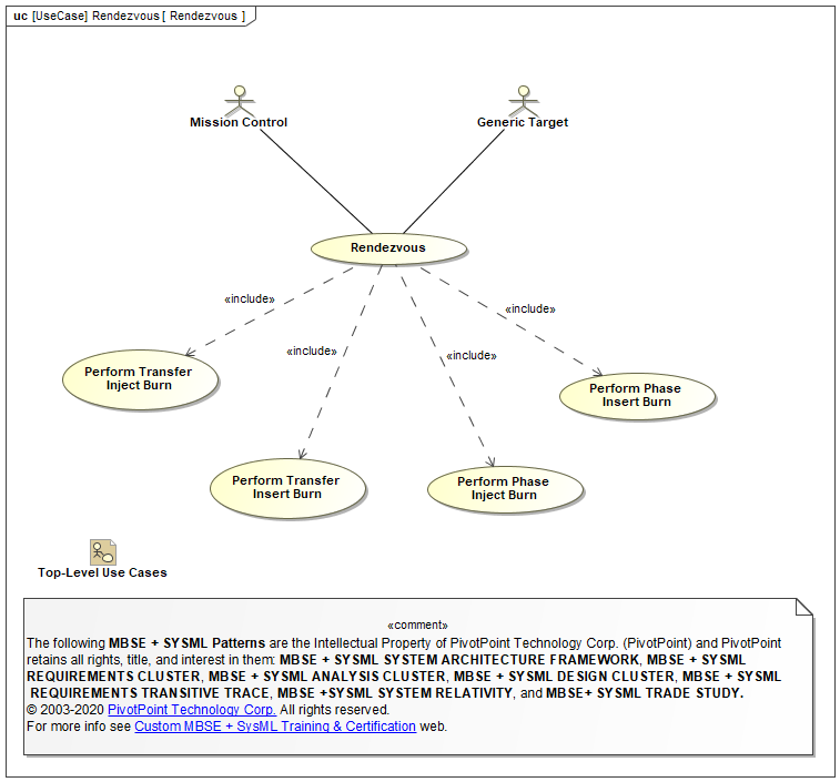
Use Case Decomposition
Diagram Properties
| Diagram Name | Diagram Type | UML 2 Analog | SDLC Usage | Essential AGILE SYSML? |
Dynamic Sim † |
Math Sim ‡ |
Auto Code Gen |
Rigor | Semi | Informal |
|---|---|---|---|---|---|---|---|---|---|---|
| Use Case diagram (uc) | Behavior * [Non-Simulatable] |
Use Case | Requirements Analysis | |||||||
Usage Notes
If Use Cases are considered to be high-level system functional requirements they should be traced to «functionalRequirement» Requirements using Refine («refine») Dependencies.
| BEST PRACTICE PATTERNS | ANTI-PATTERNS |
|---|---|
| * Restrict use for brainstorming, ConOps, "Cartoons for Executives & General s", etc. | * Examples of Use Case Modeling Antipatterns [M. El-Attar] |
| * Cut-over to high-level Activity diagrams ASAP! |
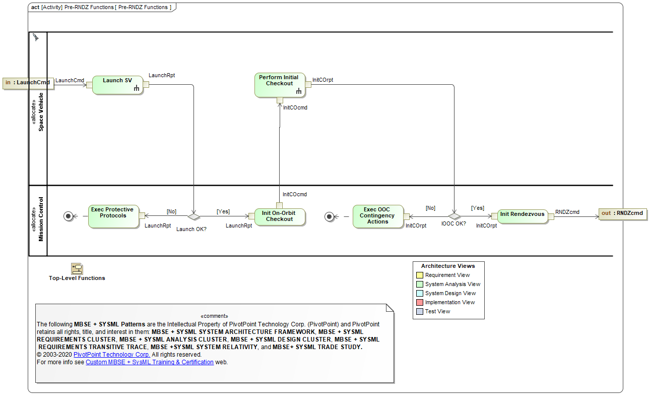
What is a SysML Activity diagram?
Definitions
Activity: An Activity (notation: rounded-rectangle or "roundangle") represents a flow of functional behaviors that may include optional Object (data) Flows. Control and Object Flows can be sequential (default) or parallel (indicated by Fork & Join Nodes) depending upon conditions.
- Action = atomic Activity, which is a primitive executable behavior.
- Control Flow = flow of functional behaviors
- Object Flow = data flow of object inputs/outputs into/from an Activity or Action.
Activity diagram (act): An Activity diagram shows system dynamic behavior using a combined Control Flow and Object (data) Flow model.
- Activities (and indirectly Activity diagrams) can be recursively decomposed ("nested") by alternating between Activity definitions and Call Behavior Action usages (See Usage Notes below.)
- Activities and Actions can be Allocated (via to Partitions that represent Control Blocks (i.e., Blocks that represent the System, Subsystems, Sub-Subsystems, ..., atomic structures);
- Data Blocks (i.e., Blocks that represent Persistent Data Stores) and Signals that contain Data Blocks can be Allocated to Activity Parameters and Action Pins;
- compare and contrast: SA/SD DFDs, FFBDs, EFFBDs,IDEF0; BPMN BPDs.
Purpose
The purpose of Activity diagrams is to specify dynamic system behaviors that Satisfy («satisfy» Dependency) system Functional Requirements using both Control and Object (data) Flows. When properly applied (See Usage Notes below) Activity diagrams are recursively scalable and simulatable.
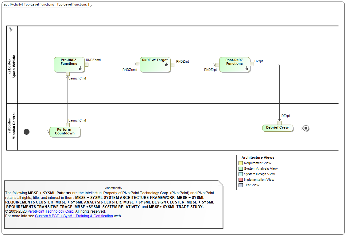
Top-Level Functions
Function Decomposition
Diagram Properties
| Diagram Name | Diagram Type | UML 2 Analog | SDLC Usage | Essential AGILE SYSML? |
Dynamic Sim † |
Math Sim ‡ |
Auto Code Gen |
Rigor | Semi | Informal |
|---|---|---|---|---|---|---|---|---|---|---|
| Activity diagram (act) | Dynamic Behavior [Simulatable] |
Activity [minor mods] |
System Analysis, Functional Analysis, System Design |
|||||||
Usage Notes
| BEST PRACTICE PATTERNS | ANTI-PATTERNS |
|---|---|
| * Recursively decompose ("nest") Activities by alternating between Activity definitions and Call Behavior usages. | * Bloctivity Anti-Pattern = Conflate Block and Activity syntax and semantics. |
| * Allocate all Activities and Actions to a Partition that represents a Control Block. | * SMactivity Anti-Pattern = Conflate State Machine and Activity syntax and semantics. |
| * Allocate Data Blocks or Signals to all Activity Parameters and Action Pins. | |
| * Ensure that all Activities Satisfy at least one Functional Requirement. |
What is a SysML Block Definition diagram?
Definitions
Block: A Block (notation: rectangle with keyword = «block») represents a system component, a modular structural unit that encapsulates its contents (Properties, Behaviors, Constraints) and supports first-class (i.e., can be drawn and directly manipulated in the model repository) Interfaces. Behaviors encapsulated by Blocks include: Operations, Signals, and State Machines. The unique interaction points for attaching and connecting ("wiring") Block Interfaces are called Ports.
- Blocks can specify software, hardware, mechanical, and wetware (persons, organizations, facilities) components.
- Blocks support both Provided (implemented or realized) and Required (used) Interfaces for both information and physical flows.
- Blocks can be recursively decomposed into Parts, where each Part must also be defined by a Block. (See Usage Notes below.)
Block Definition Diagram (bdd): A Block Definition Diagram is a static structural diagram that shows system components, their contents (Properties, Behaviors, Constraints), Interfaces, and relationships.
- Blocks can be recursively decomposed ("nested") into Parts by alternating between Block Definition Diagram (BDD) definitions and Internal Block Diagram (IBD) usages (See Usage Notes below.)
- Behaviors can either be encapsulated by Blocks (e.g., Operations, Signals, and State Machines) or Allocated (via «allocate» Dependency) to Blocks (e.g., Activities/Actions) directly or indirectly (via Interfaces).
- Blocks can be mathematically constrained via Constraint Blocks to produce mathematically simulatable Parametric diagrams.
- compare and contrast: UML 2 Class and Component diagrams; SA/SD System Context & Structure Chart diagrams; IDEF IDEF1X diagrams.
Purpose
The purpose of Block Definition Diagrams is to specify system static structures that be used for Control Objects, Data Objects, and Interface Objects. When properly applied (See Usage Notes below) Block diagrams are recursively scalable and mathematically (parametrically) simulatable (See Executable Semantics below.)
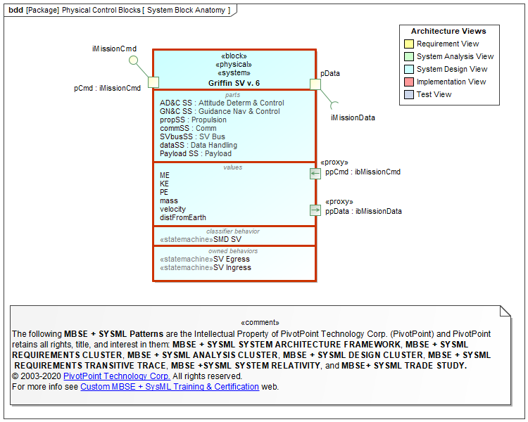
System Block Anatomy

System Context
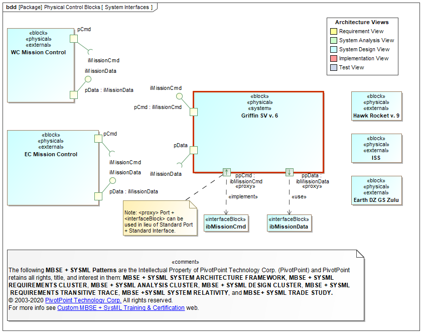
System Interfaces
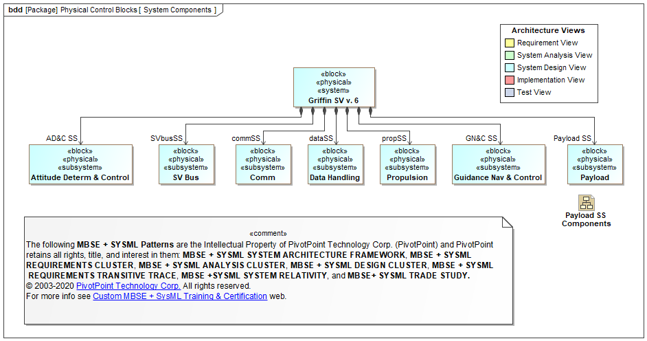
System Components
Diagram Properties
| Diagram Name | Diagram Type | UML 2 Analog | SDLC Usage | Essential AGILE SYSML? |
Dynamic Sim † |
Math Sim ‡ |
Auto Code Gen |
Rigor | Semi | Informal |
|---|---|---|---|---|---|---|---|---|---|---|
| Block Definition Diagram (bdd) | Static Structure [Black Box Definition] |
Class [moderate mods] |
System Analysis, System Design |
|||||||
Usage Notes
BDD Block Definition vs. IBD Block Usage Dichotomy
BDDs and IBDs complement each other (cf. black-box vs. white-box) and support recursive structural decomposition techniques during System Analysis & Design.
- A BDD defines a Block’s Properties, including its Part Properties (strongly owned Parts) and Reference Properties (shared Parts)
- IBD specifies Part Properties and Reference Properties usages or roles in the structural context of the Block that encapsulates them. Stated otherwise, Part Properties and Reference Properties in an IBD can have a different usages or roles depending upon how they are realized ("wired") in the IBD.
- Compare and contrast UML Specification-Realization and Type-Instance dichotomies
| BEST PRACTICE PATTERNS | ANTI-PATTERNS |
|---|---|
| * Aggressively apply Object Triad Pattern triage techniques to Blocks in order to separate Control Objects, Interface Objects, and Data Objects. | * Conflate Control Object, Interface Object, and Data Object Blocks. |
| * Recursively decompose ("nest") Block hierarchies by alternating between BDD definitions and IBD usages. | * SA/SD DFD Anti-Pattern (a.k.a., "Back to the Future circa 1980" Anti-Pattern) = Define Activity diagrams as Functional Flow diagrams without Parttions that represent Control Objects. |
| * Allocate all Activities to Partitions that represent Conrol Object Blocsk. | * Bloctivity Anti-Pattern = Conflate Block and Activity syntax and semantics. |
What is a SysML Internal Block Diagram?
Definitions
Block: A Block (notation: rectangle with keyword = «block») represents a system component, a modular structural unit that encapsulates its contents (Properties, Behaviors, Constraints) and supports first-class (i.e., can be drawn and directly manipulated in the model repository) Interfaces. Behaviors encapsulated by Blocks include: Operations, Signals, and State Machines. The unique interaction points for attaching and connecting ("wiring") Block Interfaces are called Ports.
- Blocks can specify software, hardware, mechanical, and wetware (persons, organizations, facilities) components.
- Blocks support both Provided (implemented or realized) and Required (used) Interfaces for both information and physical flows.
- Blocks can be recursively decomposed into Parts, where each Part must also be defined by a Block. (See Usage Notes below.)
Internal Block Diagram (ibd): An Internal Block Diagram is a static structural diagram owned by a particular Block that shows its encapsulated structural contents: Parts, Properties, Connectors, Ports, and Interfaces. Stated otherwise, an IBD is a "white-box" perspective of an encapsuated ("black-box") Block.
- Blocks can be recursively decomposed ("nested") into Parts by alternating between Block Definition Diagram (BDD) definitions and Internal Block Diagram (IBD) usages (See Usage Notes below.)
- Behaviors can either be encapsulated by Blocks (e.g., Operations, Signals, and State Machines) or Allocated (via «allocate» Dependency) to Blocks (e.g., Activities/Actions) directly or indirectly (via Interfaces).
- Blocks can be mathematically constrained via Constraint Blocks to produce mathematically simulatable Parametric diagrams.
- compare and contrast: UML 2 Class and Component diagrams; SA/SD System Context & Structure Chart diagrams; IDEF IDEF1X diagrams.
Purpose
The purpose of Internal Block Diagrams (IBDs) is to show the encapsulated structural contents (Parts, Properties, Connectors, Ports, Interfaces) of Blocks so that they can be recursively decomposed and "wired" using Interface Based Design techniques. When used correctly BDDs + IBDs are recursively scalable and mathematically (parametrically) simulatable (See Executable Semantics below.)
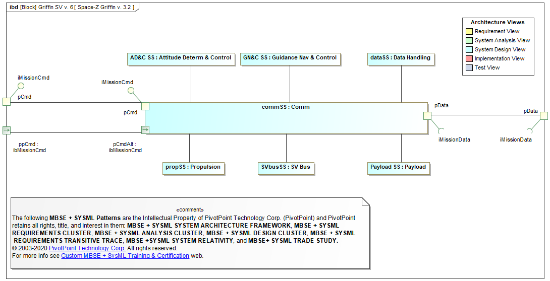
SysML IBD: Part Usage Example
Diagram Properties
| Diagram Name | Diagram Type | UML 2 Analog | SDLC Usage | Essential AGILE SYSML? |
Dynamic Sim † |
Math Sim ‡ |
Auto Code Gen |
Rigor | Semi | Informal |
|---|---|---|---|---|---|---|---|---|---|---|
| Internal Block Diagram (ibd) | Static Structure [White Box Usage] |
Composite Structure [moderate mods] |
System Analysis, System Design |
|||||||
Usage Notes
BDD Block Definition vs. IBD Block Usage Dichotomy
BDDs and IBDs complement each other (cf. black-box vs. white-box) and support recursive structural decomposition techniques during System Analysis & Design.
- A BDD defines a Block’s Properties, including its Part Properties (strongly owned Parts) and Reference Properties (shared Parts)
- IBD specifies Part Properties and Reference Properties usages or roles in the structural context of the Block that encapsulates them. Stated otherwise, Part Properties and Reference Properties in an IBD can have a different usages or roles depending upon how they are realized ("wired") in the IBD.
- Compare and contrast UML Specification-Realization and Type-Instance dichotomies
| BEST PRACTICE PATTERNS |
ANTI-PATTERNS |
|---|---|
| * Aggressively apply Object Triad Pattern triage techniques to Blocks in order to separate Control Objects, Interface Objects, and Data Objects. | * Conflate Control Object, Interface Object, and Data Object Blocks. |
| * Recursively decompose ("nest") Block hierarchies by alternating between BDD definitions and IBD usages. | * SA/SD DFD Anti-Pattern (a.k.a., "Back to the Future circa 1980" Anti-Pattern) = Define Activity diagrams as Functional Flow diagrams without Parttions that represent Control Objects. |
| * Allocate all Activities to Partitions that represent Conrol Object Blocsk. | * Bloctivity Anti-Pattern = Conflate Block and Activity syntax and semantics. |
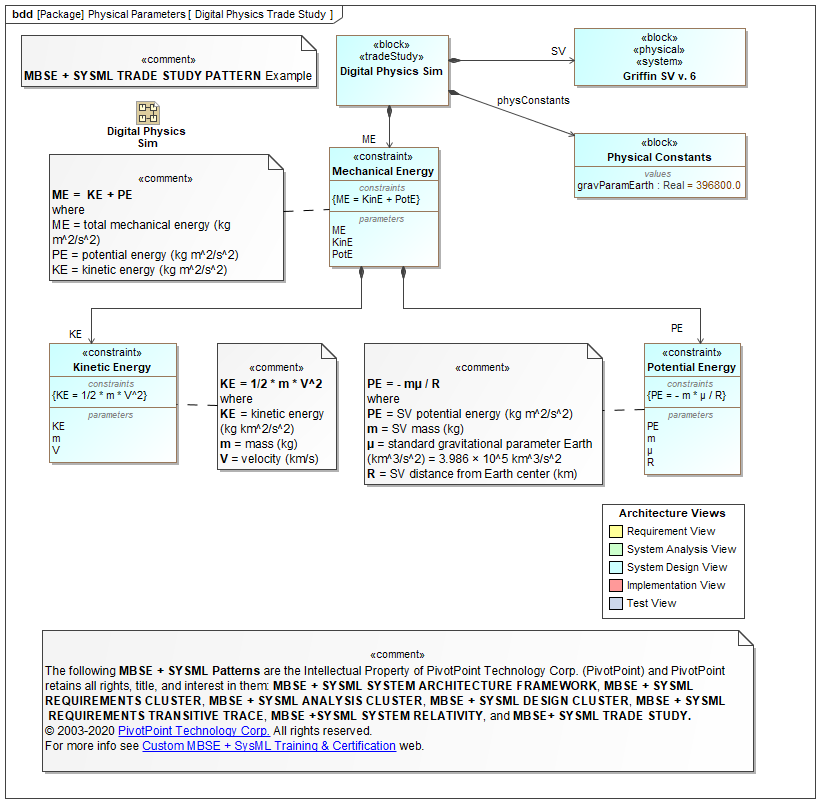
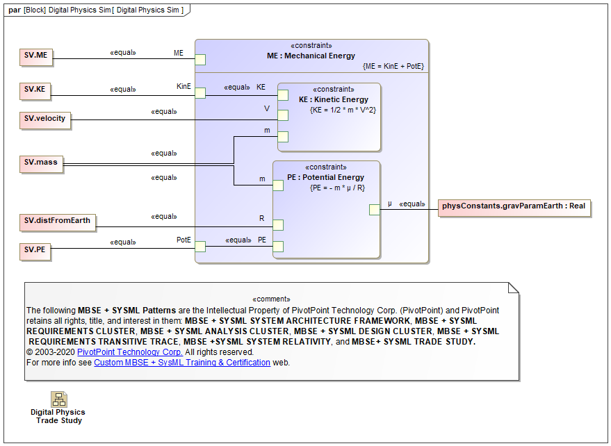
What is a SysML Parametric Diagram?
Definitions
Constraint Block: A Constraint Block (notation: rectangle with keyword = «constraint») defines a mathematical rule (Constraint) and rule Parameters, where the latter are bound to Block Value Properties so that changes to one Block Value Property will be propagated to other Block Value Properties in a manner consistent with the mathematical rule. (See Executable Semantics below.)
Parametric diagram (par): An Parametric diagram is a specialization of an Internal Block Diagram (IBD) that enforces mathematical rules (Constraints) defined by Constraint Blocks across the internal Part Value Properties bound by the Constraint Block Parameters.
- Binding Connectors (keyword = «equal») between Constraint Block Parameters and internal Part Value Properties effect constraint satisfaction (propagation)
Purpose
The purpose of Parametric diagrams (PARs) is to enforce mathematical rules across Block Value Properties. When used correctly BDDs + IBDs + PARs are recursively scalable and mathematically simulatable. (See Executable Semantics below.)
Constraint Block Usage
Diagram Properties
| Diagram Name | Diagram Type | UML 2 Analog | SDLC Usage | Essential AGILE SYSML? |
Dynamic Sim † |
Math Sim ‡ |
Auto Code Gen |
Rigor | Semi | Informal |
|---|---|---|---|---|---|---|---|---|---|---|
| Parametric Diagram (par) | Static Structure [White Box Usage] |
N/A | System Analysis, System Design |
|||||||
Usage Notes
BDD Constraint Block Definition vs. PAR Constraint Block Usage Dichotomy
- A BDD defines a Constraint Block’s mathematical rule (Constraint) and the rule's Parameters
- a PAR specifies the Binding Connector usages among Constraint Block Parameters and the Part Value Properties that are restricted by them.
Compare and contrast: BDD Block Definition vs. IBD Block Usage dichotomy; UML Specification-Realization and Type-Instance dichotomies
| BEST PRACTICE PATTERNS |
ANTI-PATTERNS |
|---|---|
| * Apply Constraint Blocks and PAR diagrams to System Designs after the BDD-IBD system architecture skeletons have stabilized. | * Applying Constraint Blocks and PAR diagrams in isolation (i.e., not integrated with BDD-IBD system architecture skeletons. |
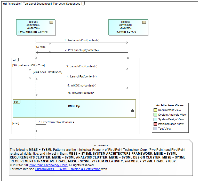
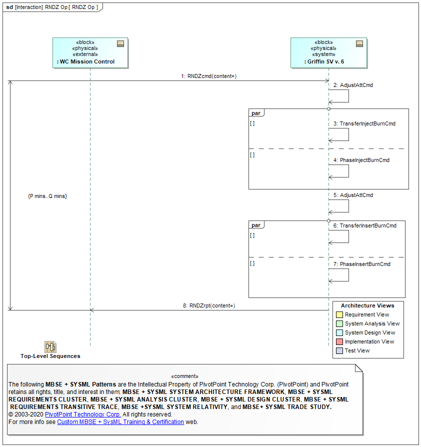
What is a SysML Sequence diagram?
Definitions
Message: A Message (notation: arrow) represents communication from one object to another, with the expectation that a useful behavior will ensue. Messages may be synchronous (notation: open arrowhead) or asynchronous (notation: black-triangle arrowhead).
Sequence diagram (sd): A Sequence diagram is a dynamic behavioral diagram that shows interactions (collaborations) among distributed objects or services via sequences of messages exchanged, along with corresponding (optional) events.
- collaborating objects or services are Parts depicted as Lifelines (notation: rectangle with a dashed vertical line below)
- Combined Fragment operators support recursive nesting and Turing Complete semantics (Alternative [alt], Optional [opt], Parallel [par], Loop [loop], etc.)
- compare and contrast: Message Sequence Charts (MSCs).
Purpose
The purpose of Sequence diagrams is to specify dynamic system behaviors as message-passing collaborations among prototypical Blocks (Parts). When properly applied (See Usage Notes below) Activity diagrams are recursively scalable and simulatable.
Top-Level Sequence
Reference Decomposition
Diagram Properties
| Diagram Name | Diagram Type | UML 2 Analog | SDLC Usage | Essential AGILE SYSML? |
Dynamic Sim † |
Math Sim ‡ |
Auto Code Gen |
Rigor | Semi | Informal |
|---|---|---|---|---|---|---|---|---|---|---|
| Sequence diagram (seq) | Dynamic Behavior [Simulatable] |
Sequence | System Design | |||||||
Usage Notes
| BEST PRACTICE PATTERNS | ANTI-PATTERNS |
|---|---|
| * Recursively decompose ("nest") Sequence diagrams by using Combined Fragement References (denoted by ref label). | * Define Messages as strings instead of reusing Block and Interface Operations and Signals. |
What is a SysML State Machine diagram?
Definitions
State: A State (notation: rounded-rectangle a.k.a. "roundangle") represents a condition or situation during the life of an object during which it satisfies some condition, performs some activity, or waits for some event.
State Machine diagram (smd): An State Machine diagram is a dynamic behavioral diagram that shows the sequences of States that an object or an interaction go through during its lifetime in response to Events (a.k.a. "Triggers"), which may result in side-effects (Actions.
Purpose
The purpose of State Machine diagrams is to specify dynamic system behaviors for time-critical, mission-critical, safety-critical, or financially-critical objects. When properly applied (See Usage Notes below) State Machine diagrams are recursively scalable and simulatable.
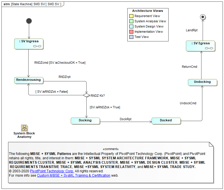
Top-Level State Machine
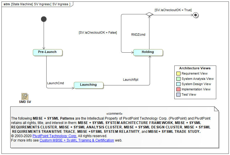
Submachine State
Diagram Properties
| Diagram Name | Diagram Type | UML 2 Analog | SDLC Usage | Essential AGILE SYSML? |
Dynamic Sim † |
Math Sim ‡ |
Auto Code Gen |
Rigor | Semi | Informal |
|---|---|---|---|---|---|---|---|---|---|---|
| State Machine diagram (stm) | Dynamic Behavior [Simulatable] |
State Machine | System Analysis, System Design |
|||||||
Usage Notes
| BEST PRACTICE PATTERNS |
ANTI-PATTERNS |
|---|---|
| * Use Activity and Sequence diagrams to specify collaborative dynamic behaviors; use State Machines selectively for time/safety/mission/financial critical objects. | * SMactivity Anti-Pattern = Conflate State Machine and Activity syntax and semantics. |
What is a SysML Package diagram?
Definitions
Package: A Package (notation: "folder" icon) is a general-purpose mechanism for organizing model elements and diagrams into groups. Packages define unique namespaces for model elements defined within their scope.
- namespace = a declarative region that provides scope for the identifiers contained within
Package diagram (pkg): A Package diagram is a static structural diagram that shows the relationships among packages and their contents. Package can be stereotyped (customized) for organizing model elements into models, views, model libraries, and frameworks.
Purpose
The purpose of Package diagram is to support the organization and management of large, complex System Architecture Models (SAMs).
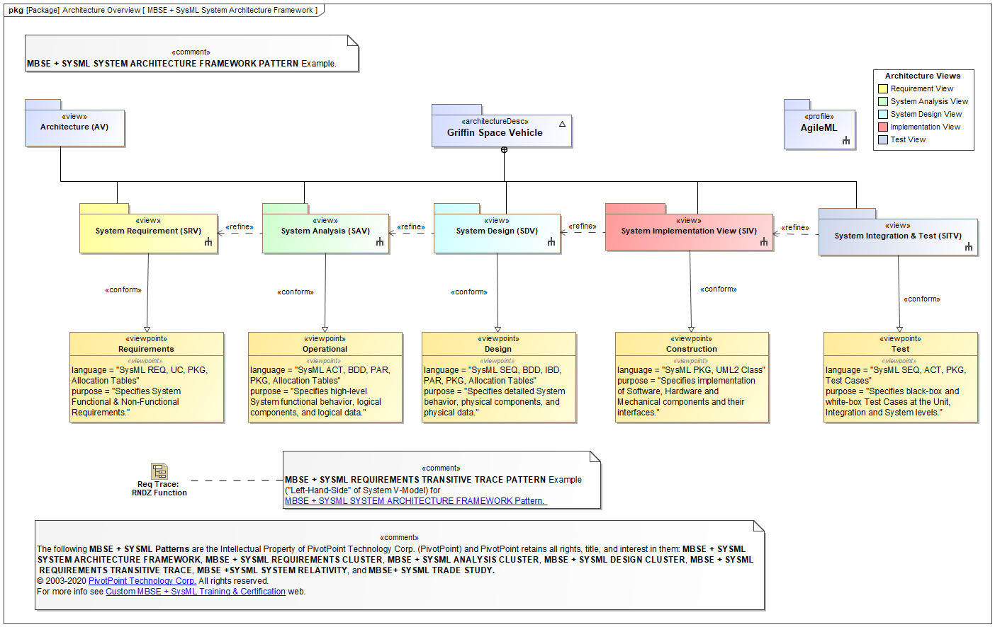
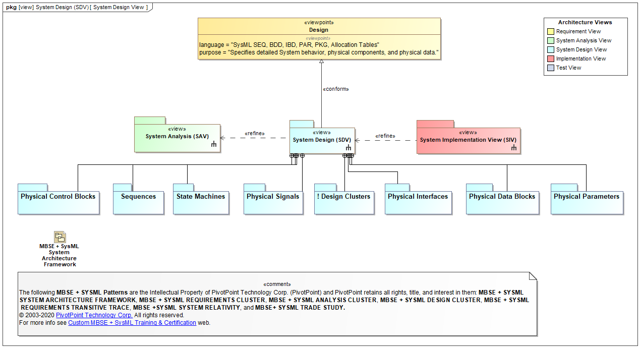
Diagram Properties
| Diagram Name | Diagram Type | UML 2 Analog | SDLC Usage | Essential AGILE SYSML? |
Dynamic Sim † |
Math Sim ‡ |
Auto Code Gen |
Rigor | Semi | Informal |
|---|---|---|---|---|---|---|---|---|---|---|
| Package diagram (pkg) | Static Structure [Grouping] |
Package [minor mods] |
All SDLC phases | |||||||
Usage Notes
| BEST PRACTICE PATTERNS | ANTI-PATTERNS |
|---|---|
| * Use a Enterprise Architecture Framework (EAF) Package Patterns to organize the complexity of your System Architecture Model. | * Fractured-Framework Anti-Pattern: Ad Hoc/Chaotic Package organization. |
What is a SysML Allocation Table?
Definitions:
Allocation: An Allocation Dependency arrow (dashed-line with open-arrow notation and keyword = «allocate») associates or maps model elements of different types, or in different hierarchies. Allocate Dependency patterns are generally useful for improving model architecture integrity (a.k.a., well-formedness) and consistency. SysML predefines the following Allocation Dependencies:
- allocations for Requirement dependencies
- allocations for Activities to Partitions (swimlanes)
Users are encourage to define their own Allocation Dependencies as needed. (See Best Practice Patterns below for examples of user-defined Allocations.)
Allocation Table: An Allocation Table is a tabular (matrix) notation for Allocation relationships, but the SysML standard does not prescribe a particular format for these so they tend to be vendor specific.
Purpose
The purpose of an Allocation Table is to define relationship matrices within and across diagram types to improve model architectural integrity (well-formedness) and consistency.
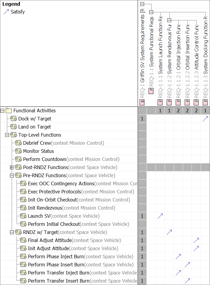
Diagram Properties
| Diagram Name | Diagram Type | UML 2 Analog | SDLC Usage | Essential AGILE SYSML? |
Dynamic Sim † |
Math Sim ‡ |
Auto Code Gen |
Rigor | Semi | Informal |
|---|---|---|---|---|---|---|---|---|---|---|
| Allocation Table | N/A [Relationship Matrix] |
N/A | All SDLC phases | |||||||
Usage Notes
| BEST PRACTICE PATTERNS | ANTI-PATTERNS |
|---|---|
| * Use Allocation Tables to define system architecture integrity (well-formedness rules) for System Analysis and System Design. | * Rely on the anemic subset of Allcoation Tables defined by the OMG SysML specification and SysML tool vendors. |
| * Use Allocation Tables to define system Verification & Validation (V&V) relationships on both sides of the System V-Model. |
TOGAF and ARCHIMATE are trademarks of The Open Group.
ENTERPRISE ARCHITECT is a trademark of Sparx Systems Pty Ltd. MAGICDRAW and CAMEO are trademarks of No Magic, Inc. RATIONAL RHAPSODY is a trademark of IBM.
All other trademarks are the property of their respective owners.